Eureka AIR delivers breakthrough ideas for toughest innovation challenges, trusted by R&D personnel around the world.

Thin film magnetic head and method of manufacturing the same

a thin film, magnetic head technology, applied in the direction of head surface, head with metal sheet core, instruments, etc., can solve the problems of information overwriting information, reducing the amount of magnetic flux, and reducing the strength of vertical magnetic field, so as to ensure overwriting characteristics and prevent adverse effects.

Inactive Publication Date: 2007-04-17
TDK CORPARATION
View PDF21 Cites 38 Cited by
  • Summary
  • Abstract
  • Description
  • Claims
  • Application Information

AI Technical Summary

Benefits of technology

[0012]The invention is designed to overcome the foregoing problems. It is a first object of the invention to provide a thin film magnetic head which is capable of both ensuring overwrite characteristics and preventing an adverse effect resulting from side erase, such as degradation in an output signal.
[0013]It is a second object of the invention to provide a method of manufacturing a thin film magnetic head, which is superior in manufacturability.
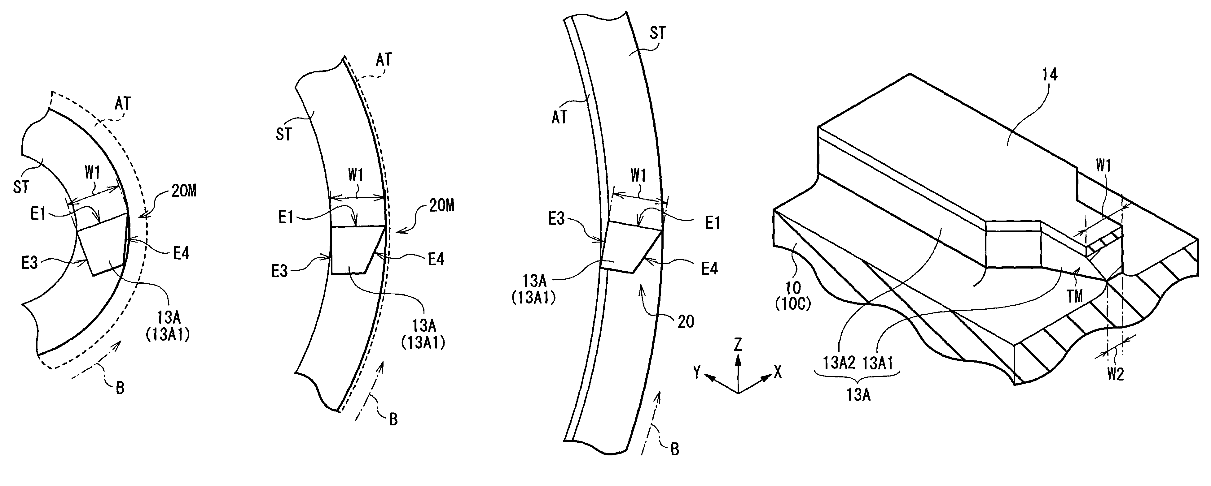
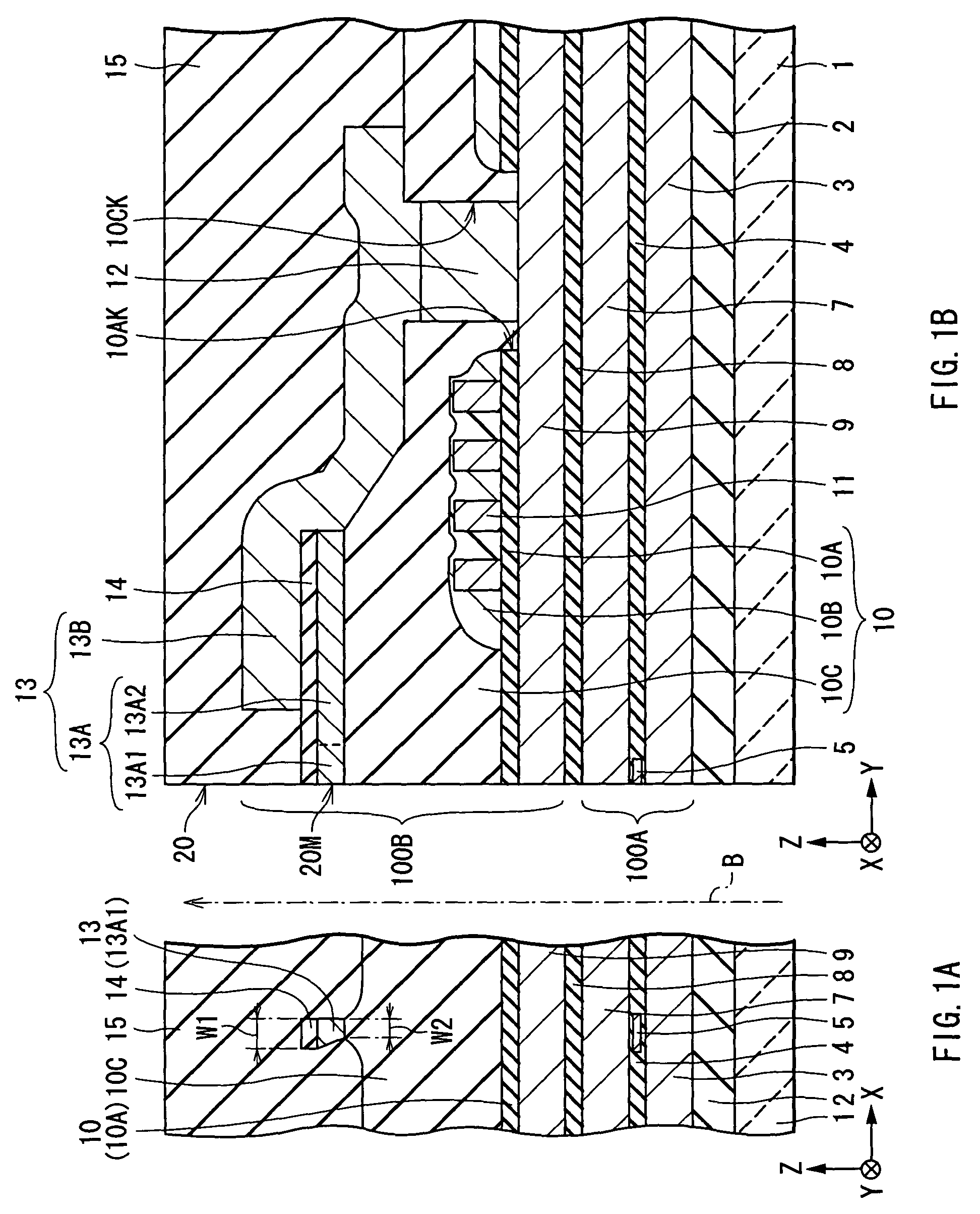
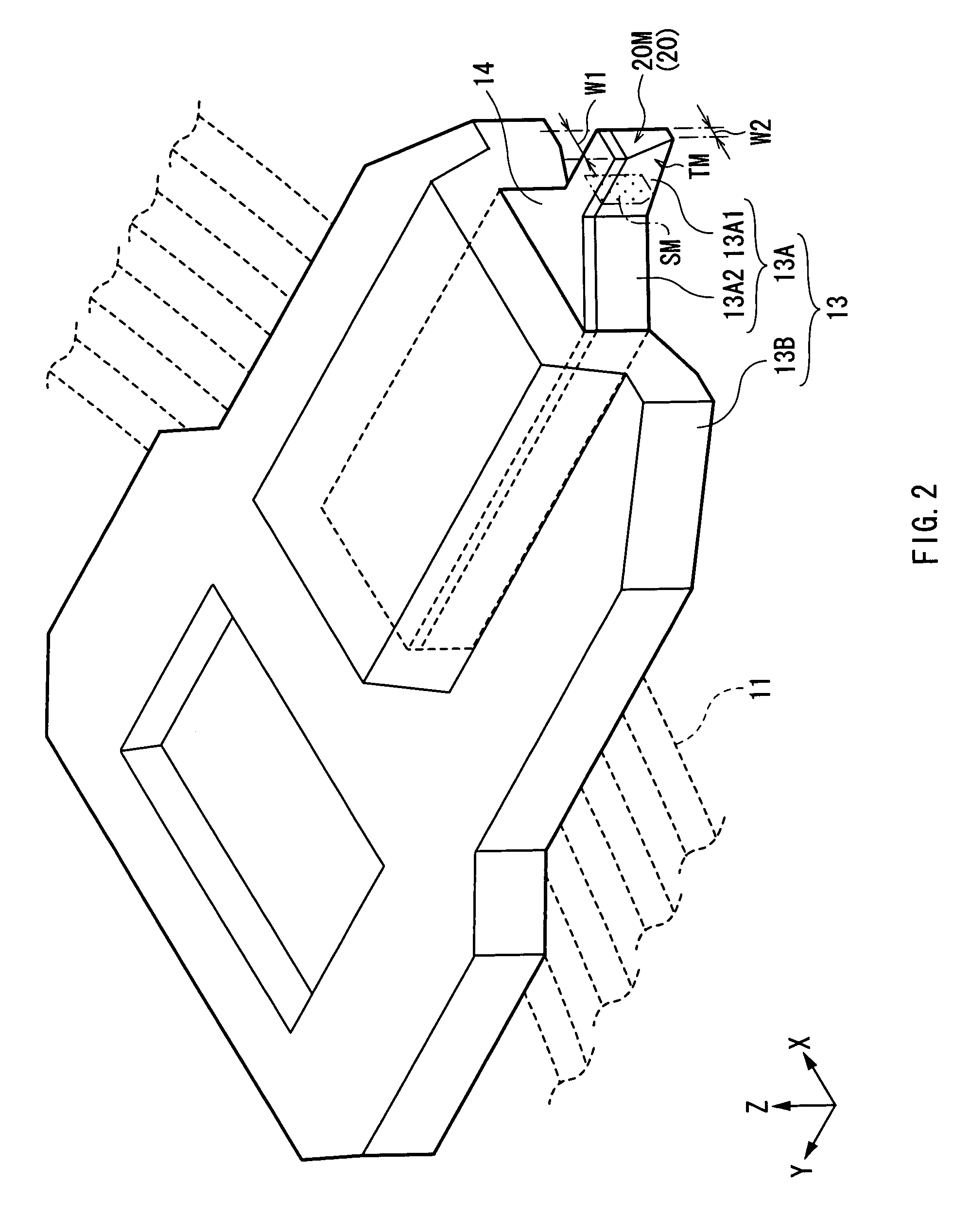
[0016]In the thin film magnetic head according to the first aspect of the invention, the magnetic pole end surface of the magnetic pole layer is configured to have the shape which is formed by removing the width increasing region, which has the width increasing gradually or stepwise from the medium outflow side to the medium inflow side in the travel direction, from the rectangular region on one side of the rectangular region along the width thereof. For example, one side of the rectangular region, which the width increasing region is removed from, is determined according to the state of occurrence of side erase. Thus, this configuration enables both ensuring the overwrite characteristics and preventing the adverse effect resulting from side erase.
[0018]In the thin film magnetic head according to the second aspect of the invention, the magnetic pole end surface of the magnetic pole layer is configured in such a manner that the width of the first edge is greater than the width of the second edge and is equal to or greater than the width of the magnetic pole end surface at any position midway between the first and second edges, and that either the third or fourth edge forms the right angle with the first edge. For example, whether the third or fourth edge forms the right angle with the first edge is determined according to the state of occurrence of side erase. Thus, this configuration enables both ensuring the overwrite characteristics and preventing the adverse effect resulting from side erase.
[0020]In the thin film magnetic head according to the third aspect of the invention, the magnetic pole end surface of the magnetic pole layer is configured to have the shape of the trapezoid having: the first edge which is located on the medium outflow side in the travel direction and is the longer side of the pair of sides parallel to each other, the first edge forming the base angles, one of which is different from the other; and the second edge which is located on the medium inflow side in the travel direction and is the shorter side of the pair of sides. For example, one base angle and the other base angle are set according to the state of occurrence of side erase so as to differ from each other. Thus, this configuration enables both ensuring the overwrite characteristics and preventing the adverse effect resulting from side erase.

Problems solved by technology

Thus, the undesired vertical magnetic field causes information to overwrite information recorded on the adjacent track.
Firstly, the reduction of the area of the end surface of the single magnetic pole type head allows obtaining an advantage in the aspect of the prevention of the adverse effect resulting from the side erase (e.g., degradation in an output signal, etc.), whereas a decrease in the area of the end surface causes a decrease in the amount of magnetic flux for use in recording emitted from the single magnetic pole type head, and this causes a decrease in vertical magnetic field strength and thus causes deterioration in overwrite characteristics which are one of important factors that determine the recording performance of the thin film magnetic head. The overwrite characteristics refer to the characteristics of overwriting information recorded on the hard disk with new information.
Secondly, it is possible that the formation of the single magnetic pole type head having the characteristic configuration having the end portion having the lower portion partly removed requires a partial removal of the lower portion of the end portion on the side of an air bearing surface using an etching technique such as FIB (focused ion beam) process having low manufacturability. Therefore, the technique is inferior in manufacturability, and etching may do damage to the single magnetic pole type head or the periphery thereof.

Method used


Image

  • Thin film magnetic head and method of manufacturing the same
  • Thin film magnetic head and method of manufacturing the same
  • Thin film magnetic head and method of manufacturing the same

Examples


examples

[0124]The following results are obtained by examining recording characteristics of the thin film magnetic head according to the embodiment.

[0125]Firstly, the results shown in FIGS. 22A and 22B are obtained by examining the overwrite characteristics of the thin film magnetic head. FIGS. 22A and 22B show the results of experiments on the overwrite characteristics of the thin film magnetic heads of the embodiment and the first and second comparative examples. In FIGS. 22A and 22B, “the vertical axis” indicates overwrite O.W. (dB). FIG. 22A shows the results which are obtained when information recorded at low density is overwritten with information recorded at high density, and FIG. 22B shows the results which are obtained when information recorded at high density is overwritten with information recorded at low density. In FIGS. 22A and 22B, the reference characters 22X, 22Y and 22Z represent the overwrite characteristic values of the second comparative example (see FIG. 5), the embodim...


PUM

PropertyMeasurementUnit
thicknessaaaaaaaaaa
thicknessaaaaaaaaaa
thicknessaaaaaaaaaa

Abstract

Provided is a thin film magnetic head which enables both ensuring overwrite characteristics and preventing an adverse effect resulting from side erase, such as degradation in an output signal. An exposed surface of a magnetic pole portion layer is configured to have the shape of an asymmetric inverted trapezoid corresponding to a remaining region which remains after removing a width increasing region in the shape of a right triangle from a rectangular region on the side of a side edge. The side edge of the exposed surface is caused to correspond to the side on which a magnetic flux emitted from the magnetic pole portion layer onto a target track of a hard disk causes information to unintentionally overwrite existing information recorded on an adjacent track. This configuration allows preventing the exposed surface from extending to the adjacent track, thus preventing the adverse effect resulting from side erase.

Description

BACKGROUND OF THE INVENTION[0001]1. Field of the Invention[0002]The invention relates to a thin film magnetic head which performs magnetic recording operation employing, for example, a vertical recording system, and a method of manufacturing a thin film magnetic head.[0003]2. Description of the Related Art[0004]Recently, a hard disk drive which records information on a hard disk, for example, has been in common use as an information recording apparatus. In the field of development of the hard disk drive, an improvement in performance of a thin film magnetic head is sought in accordance with an increase in a surface recording density of the hard disk. As recording systems of the thin film magnetic head, known are, for example, a longitudinal recording system which involves matching the direction of a signal magnetic field to the in-surface direction of the hard disk (i.e., the longitudinal direction thereof), and a vertical recording system which involves matching the direction of th...

Claims


Application Information

Patent Timeline
Patent Type & Authority Patents(United States)
IPC IPC(8): G11B5/187G11B5/00G11B5/012G11B5/127G11B5/31
CPCG11B5/1278G11B5/1871G11B5/3116G11B5/313G11B5/012G11B2005/0029
Inventor NOTSUKE, YASUYUKIODA, AKIHIROROPPONGI, TETSUYA
Owner TDK CORPARATION
Why Eureka
Eureka Blog
Learn More