Dual reflector antenna and associated methods

a dual reflector and reflector technology, applied in the field of antennas, can solve the problems of reduced beam gain, mechanical complexity of system b>20/b>, distorted beam shape, etc., and achieve the effect of low beam distortion and high feed utilization

Active Publication Date: 2007-04-17
HARRIS CORP
View PDF20 Cites 39 Cited by
  • Summary
  • Abstract
  • Description
  • Claims
  • Application Information

AI Technical Summary

Benefits of technology

[0014]In view of the foregoing background, it is therefore an object of the invention to provide an antenna system and related method that can produce multiple beams or electronically scanned beam(s) with low beam distortion and high feed utilization in a compact package.
[0015]This and other objects, features, and advantages in accordance with the invention are provided by an antenna system wherein the subreflector is positioned adjacent the focal area of the main reflector. The antenna system includes an antenna feed, and a subreflector aligned with the antenna feed. The subreflector may have a concave surface defining a vertex. The main reflector may have a parabolic or concave surface aligned with the subreflector to define an antenna focal point or area at the vertex of the subreflector. Accordingly, the antenna system provides the aperture magnification properties of the array fed Gregorian reflector configuration, but is relatively compact. The antenna focal point or area may be center fed, offset center fed, or implemented in an offset configuration to reduce blockage.

Problems solved by technology

Unfortunately, such a system 20 may be mechanically complex due to the relatively large displacement required between the main reflector 21 and the subreflector 23.
When an array feed is used with a focused reflector system, feed array elements that are not on the focal point produce beams that have significant phase error, since they are not focused, resulting in distorted beam shapes and reduced beam gain.
Consequently, such a focused system has a low feed utilization.
The drawback with a Gregorian system is the large and cumbersome geometries that are required.

Method used


Image

  • Dual reflector antenna and associated methods
  • Dual reflector antenna and associated methods
  • Dual reflector antenna and associated methods

Examples


Embodiment Construction

[0028]The invention will now be described more fully hereinafter with reference to the accompanying drawings, in which preferred embodiments of the invention are shown. This invention may, however, be embodied in many different forms and should not be construed as limited to the embodiments set forth herein. Rather, these embodiments are provided so that this disclosure will be thorough and complete, and will fully convey the scope of the invention to those skilled in the art. Like numbers refer to like elements throughout, and prime and multiple prime notation are used to indicate similar elements in alternate embodiments.

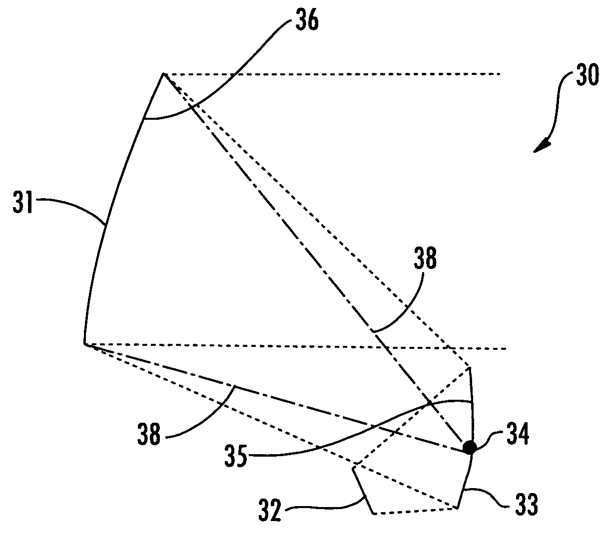
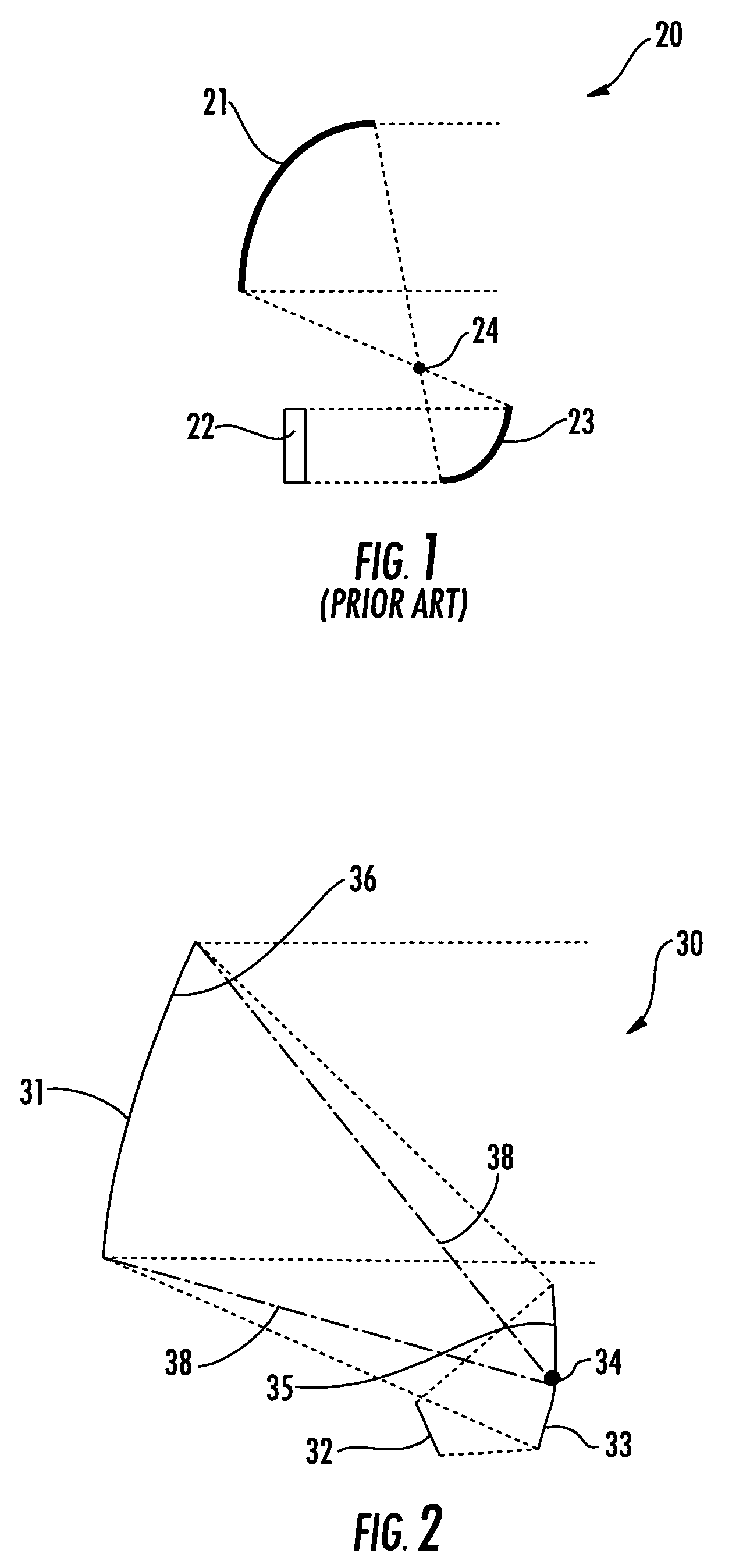
[0029]The antenna system 30 according to the invention is now described with reference to FIGS. 2 and 3. The antenna system 30 includes an antenna feed 32. A subreflector 33 is aligned with the antenna feed 32 and has a concave surface 35 defining a vertex 34. A main reflector 31 having a concave surface 36 is aligned with the subreflector 33 to define an offset a...


PUM


Abstract

An antenna system includes an antenna feed aligned with a subreflector and a main reflector. The subreflector has a concave surface defining a vertex. A main reflector having a concave surface is aligned with the subreflector to define an antenna focal area at the vertex of the subreflector. The antenna feed may be a phased array or fixed antenna feed. The antenna system may further include a controller cooperating with the phased array antenna feed for beamsteering or beamforming. The controller may cooperate with the phased array antenna feed to define and steer multiple beams, at different frequencies, for example.

Description

FIELD OF THE INVENTION[0001]The invention relates to the field of antennas, and, more particularly, to offset reflector antennas and related methods.BACKGROUND OF THE INVENTION[0002]An antenna is used to capture electromagnetic energy when operating in a receive mode, and to radiate such energy when in a transmitting mode. Accordingly, an antenna is a typical part of a communication system that also includes a transmitter and receiver, for example. To increase the antenna aperture, one or more reflectors may be arranged adjacent an antenna feed. An array feed including multiple elements may be used with such a reflector system to provide multiple beams or electronic scan capability.[0003]U.S. Pat. No. 6,236,375 to Chandler et al. discloses a reflector antenna including a feed array, a subreflector, and a main reflector, which are oriented to define an offset Gregorian antenna geometry. The antenna feed includes a plurality of separate feeds that are aligned on a predetermined contou...

Claims


Application Information

Patent Timeline
Patent Type & Authority Patents(United States)
IPC IPC(8): H01Q13/00
CPCH01Q1/288H01Q3/2658H01Q19/192H01Q25/007Y10S343/02
Inventor TURNER, GREGORY M.
Owner HARRIS CORP
Why Eureka
Try Eureka