
Illuminated anti-trip cable duct

a technology of anti-trip cable and illumination, which is applied in the direction of optical elements, instruments, and ways, can solve the problems of long illumination runs, open circuits or short circuits, and the cable itself presents a triphazard, etc., and achieves the effect of maintaining suitability for use and long illumination runs

Active Publication Date: 2007-04-10
MOORE HASKELL
View PDF15 Cites 13 Cited by
  • Summary
  • Abstract
  • Description
  • Claims
  • Application Information

AI Technical Summary

Benefits of technology

"The present invention is an illuminated anti-trip cable duct that can be used to protect wires that cross pathways. It can also be used to illuminate raceways or paths. The duct is easy to install and can be cut to any length. It can be cascaded together for long illumination runs. The duct comes in different colors to match the decor of the surroundings. It can also be programmed to blink, flash, or run through a programmed sequence of events. The power source can be either an internal battery pack or an external power supply. The duct can be provided in rolled lengths for easy shipping, warehousing, and job site installation. The invention is an attractive alternative to non-illuminated anti-trip ducts."

Problems solved by technology

While the common cable duct is intended to minimize trip hazard, the cable duct itself often presents a trip hazard, since it is designed to lie almost flat on the floor and is typically manufactured out of material that is usually neutral in color.
The reason for this impracticality is that the wires that would carry power to light bulbs would be cut at an arbitrary point, causing an open circuit or a shorted circuit and the lighting would fail.
While there may be long felt need for a versatile illuminated cable duct, the limitations of typical rope or string lighting have prevented reaching a practical solution.

Method used


Image

  • Illuminated anti-trip cable duct
  • Illuminated anti-trip cable duct
  • Illuminated anti-trip cable duct

Examples


Embodiment Construction

[0025]While the invention will be described in connection with its preferred embodiments, it will be understood that the invention is not limited thereto. On the contrary, it is intended to cover all alternatives, modifications, and equivalents, which may be included within the spirit and scope of the invention, as defined by the appended claims.

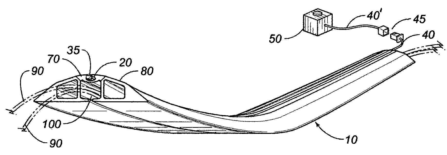
[0026]A typical embodiment of the present invention is illustrated in FIG. 1, FIG. 2, and FIG. 3. In FIG. 1, cable duct 10 is shown with a cable compartment 100 running longitudinally along the axis of cable duct 10. Cables 90 are shown protruding from cable compartment 100. Cable 90 represents one or more cables which cable duct 10 is designed to protect. A portion of cable duct 10 is manufactured with a light transmission window 70 composed of a light transmitting material and running longitudinally along the axis of, and typically on the top side of, cable duct 10. Light transmission window 70 may be composed of any material capable of tr...


PUM


Abstract

The present invention provides a pleasant illuminated anti-trip cable duct for use in protecting wires that cross pathways. The illuminated anti-trip cable duct may also be used to illuminate raceways or paths, such as aisles in auditoriums or churches. The anti-trip cable duct incorporates an integrated light transmission window and electroluminescent wire. Installation is straightforward and very similar to installation of standard, non-illuminated cable duct. Unlike rope or string lighting, which may not be arbitrarily cut, the present invention may be cut to any arbitrary length at the job site, provided that a minimum length is used. Lengths of the present invention may be cascaded together, enabling long illumination runs. The present invention may be provided in rolled lengths, adding to ease in shipping, warehousing, and job site installation. Little additional skills are required for installation, making the present invention an attractive alternative to typical non-illuminated anti-trip duct.

Description

REFERENCE[0001]Pursuant to 35 U.S.C. 119(e)(1), reference is hereby made to earlier filed provisional Patent Application No. 60 / 504,864 to Haskell Moore for Illuminated Anti-Trip Cable Duct of filing date Sep. 22, 2003.FIELD OF THE INVENTION[0002]The present invention relates generally to devices that reduce any tripping hazard from laid cables.BACKGROUND OF THE INVENTION[0003]The present invention improves common ducted cord covers used to conceal electronic cables or hoses. Typical names for ducted cord covers include “cable cover”, “cord cover”, “cord protector”, “raceway” and “cable duct”. The common cable duct is typically a semi-flexible piece of material with a channel that allows a cable or hose to be concealed inside.[0004]The purpose of a cable duct is to minimize the trip hazard and protect cables or hoses when they are lying on the floor and situated in a location where people could reasonably be expected to come in contact with them. While the common cable duct is inten...

Claims


Application Information

Patent Timeline
Patent Type & Authority Patents(United States)
IPC IPC(8): G02B6/00B61K13/00E01B7/28H02G3/04
CPCH02G3/0481
Inventor MOORE, HASKELL
Owner MOORE HASKELL
Learn More