Metal driving belt

Inactive Publication Date: 2007-04-10
VAN DOORNES TRANSMISSIE BV
View PDF17 Cites 2 Cited by
  • Summary
  • Abstract
  • Description
  • Claims
  • Application Information

AI Technical Summary

Benefits of technology

[0009]In order largely to avoid the above-mentioned limitations and disadvantages of the known solutions, the invention includes the presence of additional contact surfaces on the transverse elements situated radially outside or above the openings on axial ends of the head part. In the driving belt according to the invention an effective point of application of the friction force between the transverse element and a pulley is moved in the radial direction outwards, or upwards, in other words in the direction of the tilting line, so that the above-mentioned couple of forces advantageously can be smaller. With a suitable choice of the radial and axial positions of the contact surfaces of the body part and of the additional contact surfaces of the head part and of their dimensions, it can be ensured that an effective point of application of the last-mentioned friction force in the radial direction substantially coincides with the radial position of the tilting line. If desired, the relatively low internal friction force between the tension element and the transverse element can also be taken into account, by making the above-mentioned point of application act, depending on the internal friction force, slightly above or slightly below the tilting line.
[0010]The transverse element according to the invention has the advantage that the projection and the hole can be made smaller, in other words less high and less deep, or it may even be possible to dispense with them entirely. Advantages derived from this are a smaller dimension in the longitudinal direction or thickness of the transverse element, simpler manufacture, or a reduction in weight of the driving belt. The benefit and the application of these advantages in the design, the manufacture and the use of the driving belt are known from the last-mentioned European application. Moreover, the tilting line of the transverse element according to the present invention can be localised near the underside of the above-mentioned openings, so that a difference in speed between the transverse elements and the tension element advantageously can be minimal.

Problems solved by technology

Such a displacement can in particular occur where the driving belt is wedged between the pulley sheaves and results in tilting of the transverse element relative to the radial direction.
As a result of the above-mentioned imbalance, a couple of forces arises on the transverse element, so that the latter acquires the tendency to tilt.
This slipping would be at the expense of the efficiency of the power transmission, and there would also be a risk of damage to the driving belt and / or the pulleys.
For instance, the projection and the hole are subject to wear during use of the driving belt, as a result of which the driving belt can fail with the passage of time.
However, in such a design a difference in speed in the longitudinal direction between the tension element and the transverse elements will be greater, and consequently also the above-mentioned internal friction.
All the above has an adverse effect on the efficiency of the transmission in which the driving belt is being used.
Besides, it can be expected that the increasingly unequal distribution of the mass of the transverse element above and below the tilting line will adversely affect a desired movement and orientation of the transverse element during operation.

Method used


Image

  • Metal driving belt
  • Metal driving belt

Examples


Embodiment Construction

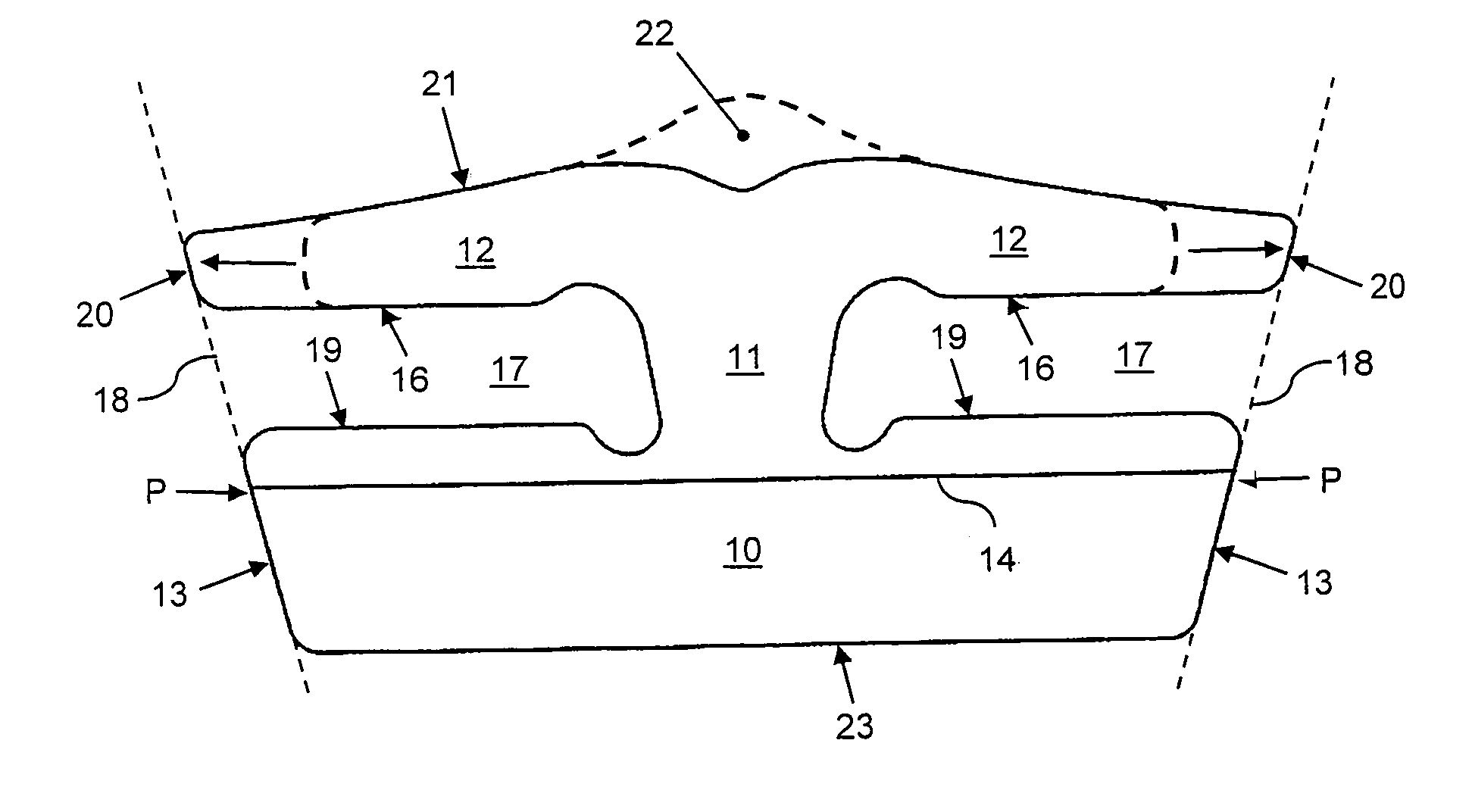
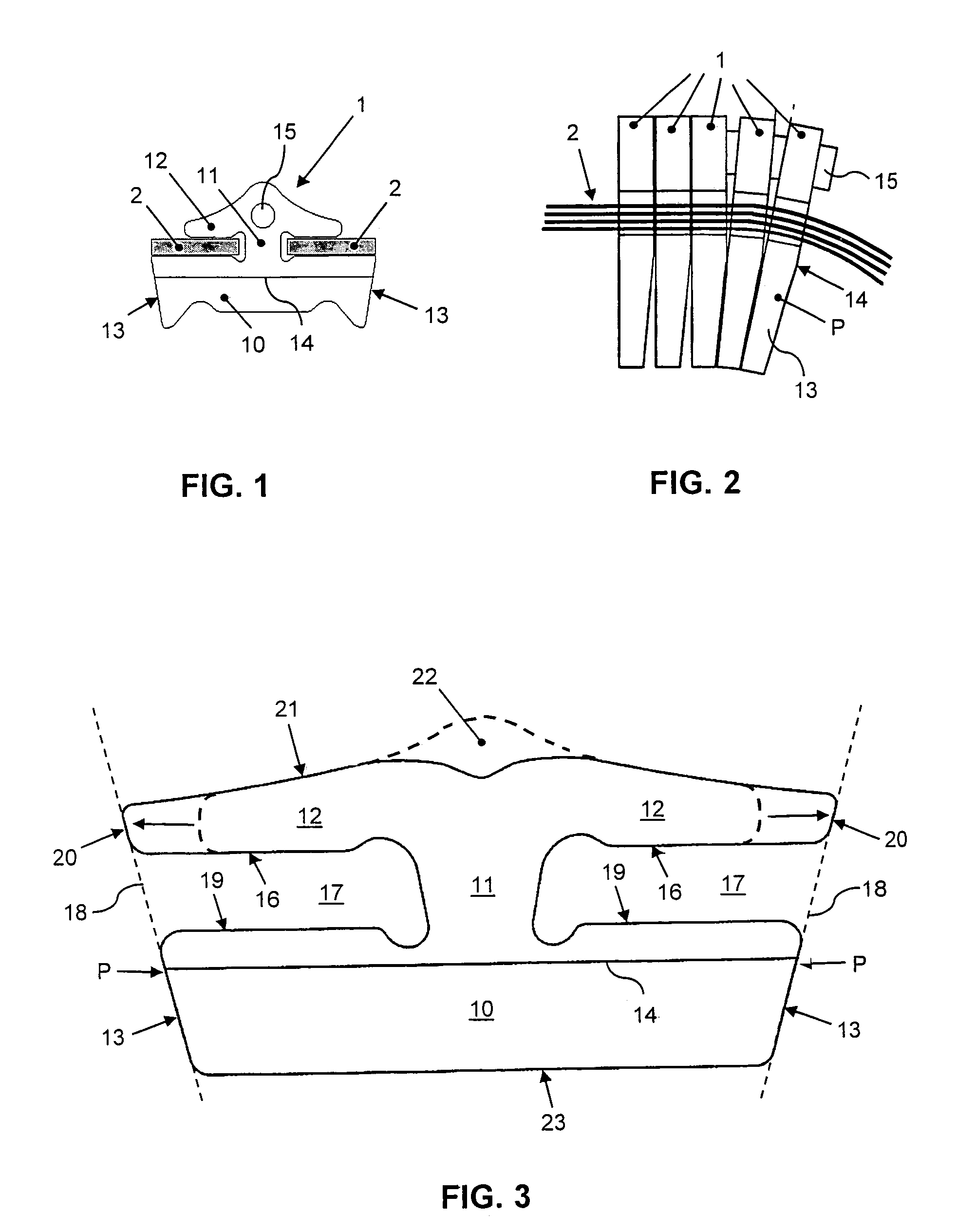
[0015]FIGS. 1–2 show diagrammatically a cross section of the known driving belt and also a segment of the driving belt in side view. The cross-section shows a two-part tension element 2 in cross section and a transverse element 1 in front view. The transverse element 1 is provided with a substantially trapezium-shaped body part 10 and a substantially arrowhead-shaped head part 12, which parts are interconnected in a neck part 11 of the transverse element 1. Openings are defined on either side of the neck part 11, between the body part 10 and the head part 12, in each of which openings a part of the tension element 2 is accommodated. The front view further shows the contour of a projection 15 in the head part 12, and also the position of a tilting line 14 in the body part 10. The side view shows a number of transverse elements 1, both in a relationship parallel to each other and in a relationship rotated in relation to each other, such as that which occurs between sheaves of a pulley...


PUM


Abstract

Driving belt provided with an enclosed tension element and metal transverse elements accommodated so as to be movable in a longitudinal direction along the tension element. The transverse elements each comprise a body part, a head part and a neck part therebetween. On either side of the neck part between the body part and the head part two axially oriented openings are present, for accommodating in each a part of the tension element. The body part includes side contact surfaces oriented substantially in an axial direction and diverging from each other in the radial direction, and with a substantially axially oriented tilting line and in which an upper limit of an opening formed by the head part extends in the axial direction at least to an imaginary line, which extends from the radially lower limit to the radially upper limit of the respective opening in line with a contact surface.

Description

BACKGROUND OF THE INVENTION[0001]The present invention relates to a metal driving belt for a continuously variable transmission, as described below. Such driving belts are generally known, for example from European Patent Application EP-A-0 522 612 in the name of the applicant. Such driving belts comprise rigid transverse elements, usually made entirely of metal, which are likewise generally known per se, and which are accommodated in the driving belt so that they are movable along an endless tension element. The tension element comprises two parts, each of which is formed by a number of thin, flat rings accommodated around one another, and each accommodated in a laterally or axially oriented opening of the transverse element.DESCRIPTION OF THE RELATED ART[0002]The known driving belt is used in a transmission, in particular for driving relatively heavy vehicles, such as a motor car or a lorry, and for this purpose is accommodated in a press fit between the sheaves of a primary, gene...

Claims


Application Information

Patent Timeline
IPC IPC(8): F16G1/22F16G5/16
CPCF16G5/16
Inventor VAN DER MEER, CORNELIS JOHANNES MARIAPRINSEN, LUCAS HENDRICUS ROBERTUS MARIAVAN LITH, JOHANNES HENDRIKUS
Owner VAN DOORNES TRANSMISSIE BV
Why Eureka
Try Eureka