
Projector type vehicle headlamp

a projector-type headlamp and headlamp technology, applied in the direction of fixed installation, transportation and packaging, light and heating equipment, etc., can solve the problem of oncoming vehicles being dazzled, and achieve the effect of safe driving of automobiles, effective suppression of glare emission, and improved visibility

Active Publication Date: 2007-04-10
KOITO MFG CO LTD
View PDF5 Cites 44 Cited by
  • Summary
  • Abstract
  • Description
  • Claims
  • Application Information

AI Technical Summary

Benefits of technology

[0006]The present invention has been made in view of such circumstances, and an object of the present invention is to prevent the emission of high beam in the process where the light distributions are switched over between the other beam than the high beam and the low beam.
[0015]As is clear from the description that has been made heretofore, according to the projector type vehicle headlamp set forth in the first aspect of the invention, the high beam is not emitted in the process where the light distribution is switched over between the low beam and the another beam, and hence there is no risk that oncoming vehicles are dazzled.
[0016]In addition, since the light distribution can be switched over speedily between the low beam, which is used most frequently, and the high beam or the other beam, the projector type vehicle headlamp of the invention can contribute to the safety driving of automobiles.
[0017]According to the second aspect of the invention, the emission of glare is effectively suppressed in the be am switching over process, and hence there is no risk that oncoming vehicles are troubled.
[0018]According to the third aspect of the invention, since the clear cut-off line of the selected beam becomes clear, the visibility is improved.
[0019]Further, the emission of glare is effectively suppressed in the beam switching over process, and hence there is no risk that oncoming vehicles are troubled. In addition, the clear cut-off line of the selected beam becomes clear, and hence, the visibility is improved.

Problems solved by technology

Therefore, when the light distributions are switched over from the low beam, which is used most frequently, to the another beam, or from the another beam to the low beam, it is inevitable that the high beam is emitted, and hence there has been caused a problem that an oncoming vehicle may be dazzled.

Method used


Image

  • Projector type vehicle headlamp
  • Projector type vehicle headlamp
  • Projector type vehicle headlamp

Examples


Embodiment Construction

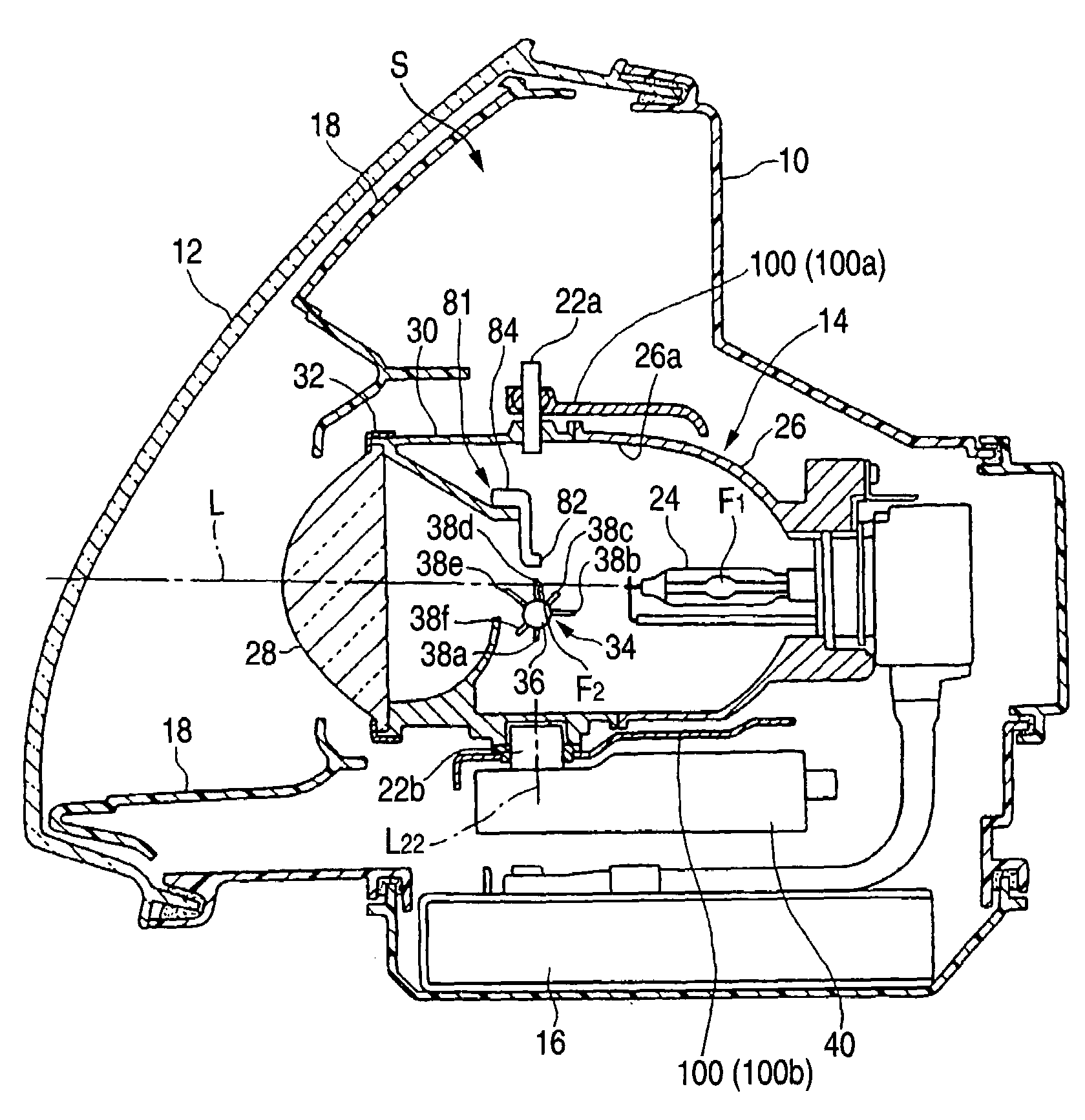
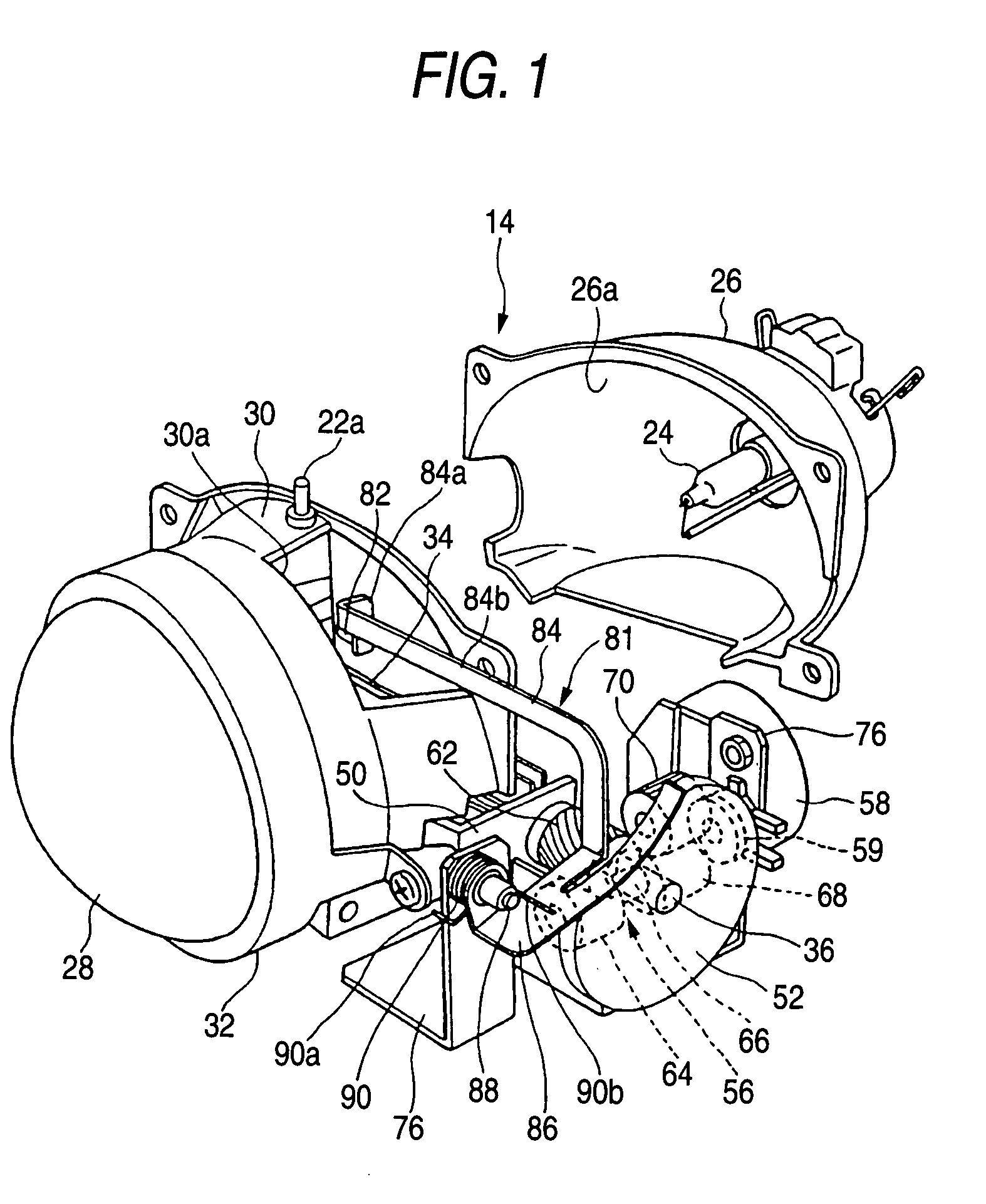
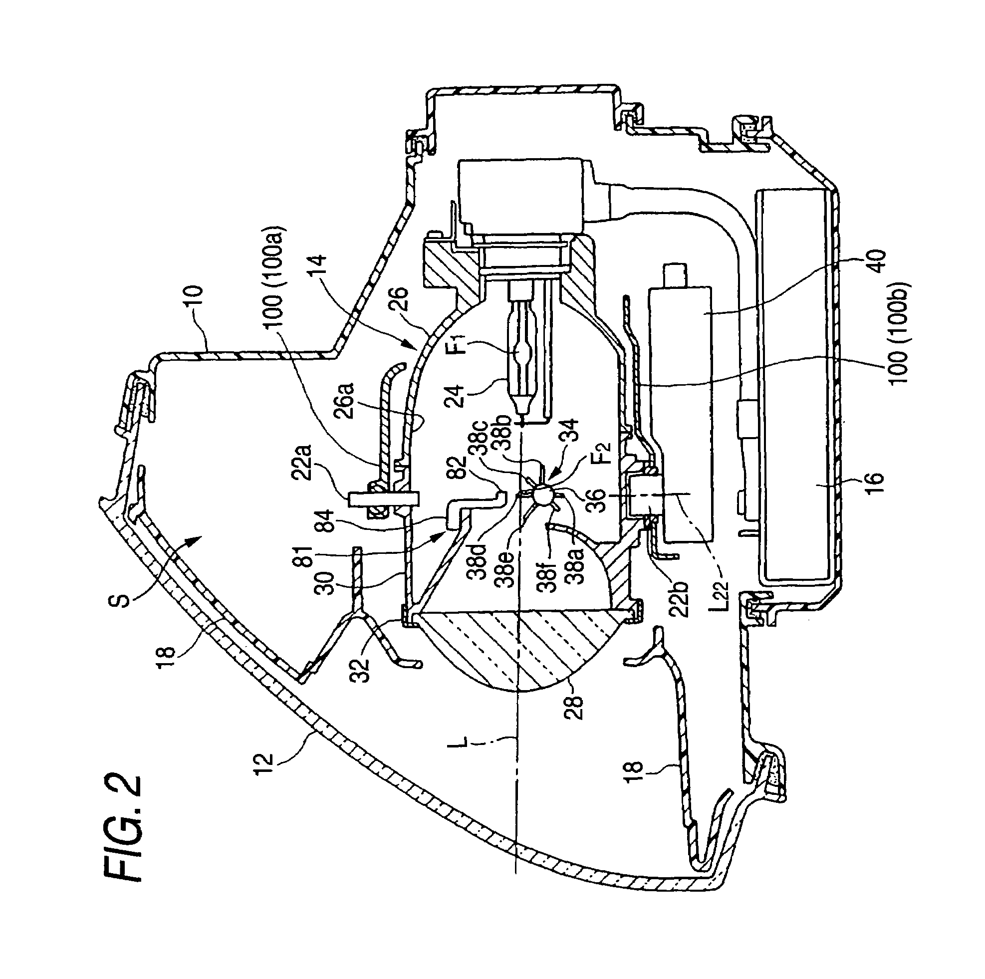
[0040]Next, modes for carrying out the invention will be described based on embodiments of the invention. FIGS. 1 to 5 illustrates a projector type vehicle headlamp of an embodiment of the invention, in which FIG. 1 is an exploded perspective view of a light projecting unit which is a main part of the projector type automobile headlamp, FIG. 2 is a longitudinal sectional view of the same headlamp at an optical axis position thereof, FIG. 3 is a side view of the same light projecting unit, FIG. 4 is a partially sectional plan view of the same light projecting unit, and FIG. 5 is a rear view of the same light projecting unit that is integrated into a unit frame with a reflector being removed therefrom, as viewed from the rear.

[0041]In these drawings, a lamp body10 of the projector type vehicle headlamp is formed into a container-like shape, and a front lens 12 is assembled to a front opening in the lamp body 10 to thereby define a lamp compartment S (refer to FIG. 2). A light projecti...


PUM


Abstract

A projector type vehicle headlamp comprises a reflector, a light source, a projection lens, a rotational shade to shield part of light reflected on the reflector so as to be directed towards the projection lens and a motor for driving the rotational shade based on a light distribution switching over operation. In the headlamp, a high beam corresponding light shielding plate and an another beam corresponding light shielding plates are disposed on the rotational shade on both sides of a low beam corresponding light shielding plate, so that the light distributions are attempted to be switched over speedily between the low beam and the another beams and the generation of glare is attempted to be prevented.

Description

[0001]This application claims foreign priority based on Japanese patent application No. JP-2004-070067, filed on Mar. 12, 2004, the contents of which is incorporated herein by reference.BACKGROUND OF THE INVENTION[0002]The present invention relates to a projector type headlamp in which reflected light from a substantially cup-shaped reflector is projected and distributed forward by a projection lens, and more particularly to a projector type vehicle headlamp which can change over light distributions by rotating a shade.[0003]Disclosed in JP-B-06-048601 is a projector type vehicle headlamp in which a light source bulb is disposed near a primary focal point of a reflecting mirror, light emitted from the light source bulb is reflected on the reflecting mirror, the reflected light is made to converge to a secondary focal point near a meridional image plane of a convex lens and a rotational shade is disposed. The rotational shade has a rotational axis within a plane which intersects with...

Claims


Application Information

Patent Timeline
Patent Type & Authority Patents(United States)
IPC IPC(8): B60Q1/00F21S8/10F21S8/12F21V7/08F21V14/00F21V14/08F21W101/10F21Y101/00
CPCF21S48/1794F21S41/698
Inventor SUGIMOTO, ATSUSHIFUKUCHI, HIDEKI
Owner KOITO MFG CO LTD
Learn More