
Composite high frequency component and mobile communication device including the same

a high frequency component and mobile communication technology, applied in the field of composite high frequency components and mobile communication devices, can solve the problems of complicated control of the high frequency switch for transmission, distortion problem with respect to the off-side high frequency switch, and increase the size of the dual-band portable telephone (mobile communication devices), so as to simplify the control of the transmission

Inactive Publication Date: 2007-04-03
MURATA MFG CO LTD
View PDF39 Cites 77 Cited by
  • Summary
  • Abstract
  • Description
  • Claims
  • Application Information

AI Technical Summary

Benefits of technology

The present invention provides a composite high frequency component that can be used in a microwave circuit, which is small in size and has low loss. The component includes a diplexer, high frequency switches, and filters integrated into a ceramic multi-layer substrate. The high frequency switches separate the signal paths for transmission and reception, and the filters are introduced in the signal paths. The use of a composite high frequency component simplifies the matching and adjustment of the diplexer and high frequency switches, and reduces the number of elements needed for the circuit. The composite high frequency component can be used in a mobile communication device, which is small and has high quality. The use of chip coils in the high frequency switches reduces loss and expands bandwidth. The invention also provides a mobile communication device that includes the composite high frequency component.

Problems solved by technology

This causes the trouble that the dual band portable telephone (mobile communication device) is increased in size.
Thus, during the transmission, the high frequency switches of the DCS system and the GSM system are differently operated, which causes the distortion problem with respect to the off-side high frequency switch.
Furthermore, it is troublesome that the control of the high frequency switches for the transmission becomes complicate.
Thus, there is the problem that the size of the triple band portable telephone (mobile communication device) is large in size.

Method used


Image

  • Composite high frequency component and mobile communication device including the same
  • Composite high frequency component and mobile communication device including the same
  • Composite high frequency component and mobile communication device including the same

Examples


first embodiment

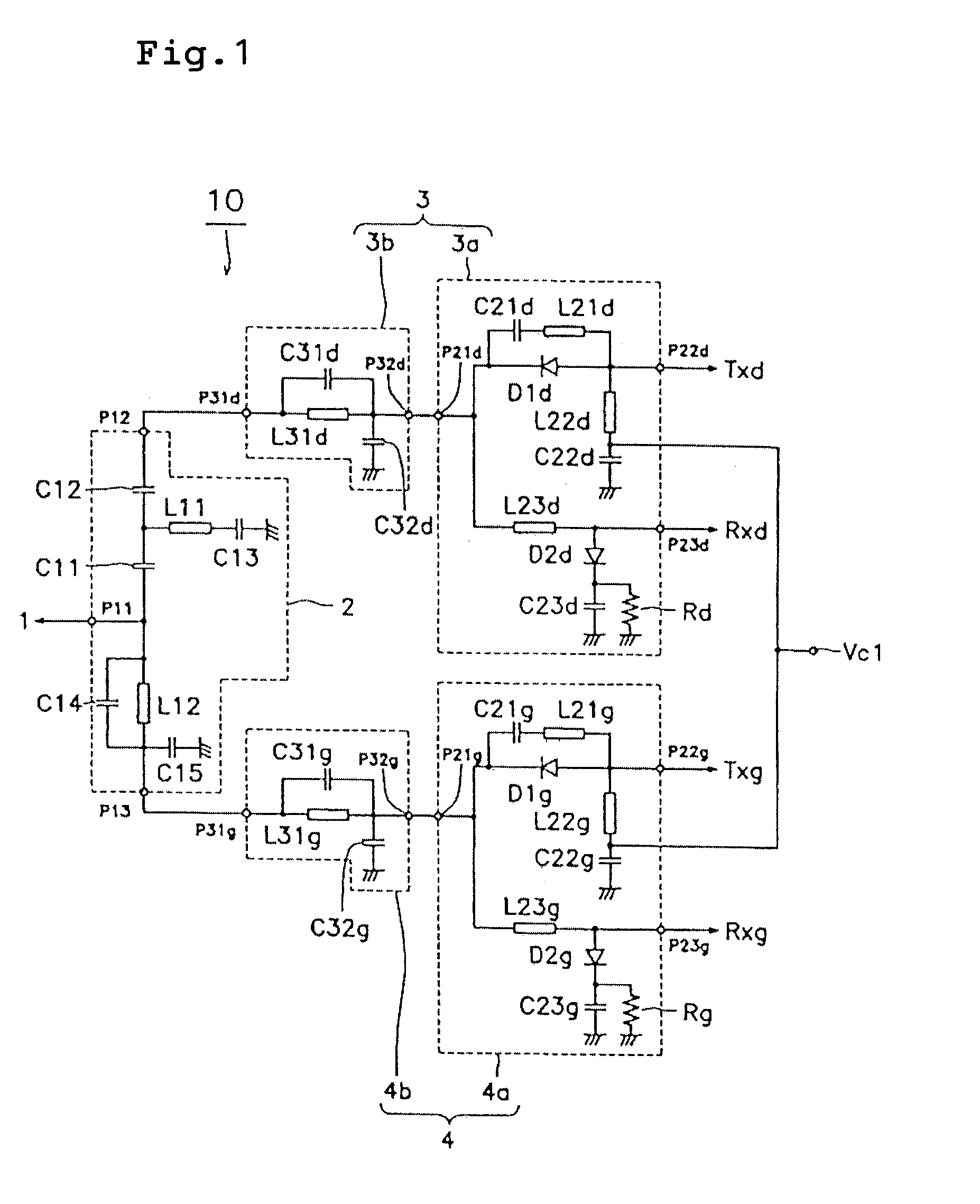
[0078]FIG. 1 is a circuit diagram of a composite high frequency component in accordance with the present invention. A composite high frequency component 10 is composed of the diplexer 2 and the high frequency switch 3a and the notch filter 3b which make up the DCS system 3, and the high frequency switch 4a and the notch filter 4b which constitute the GSM system 4.

[0079]The antenna 1 is connected to a first port P11 of the diplexer 2, a first port P31d of the notch filter 3b of the DCS system 3 to a second port P12, and a first port P31g of the notch filter 4b of the GSM system 4 to a third port P13, respectively.

[0080]In the DCS system 3, a first port P21d of the high frequency switch 3a is connected to a second port P32d of the notch filter 3b, the transmission section Txd to a second port P22d of the high frequency switch 3a, and the reception section Rxd to a third port P23d, respectively.

[0081]Further, in the GSM system 4, a first port P21g of the high frequency switch 4a is con...

second embodiment

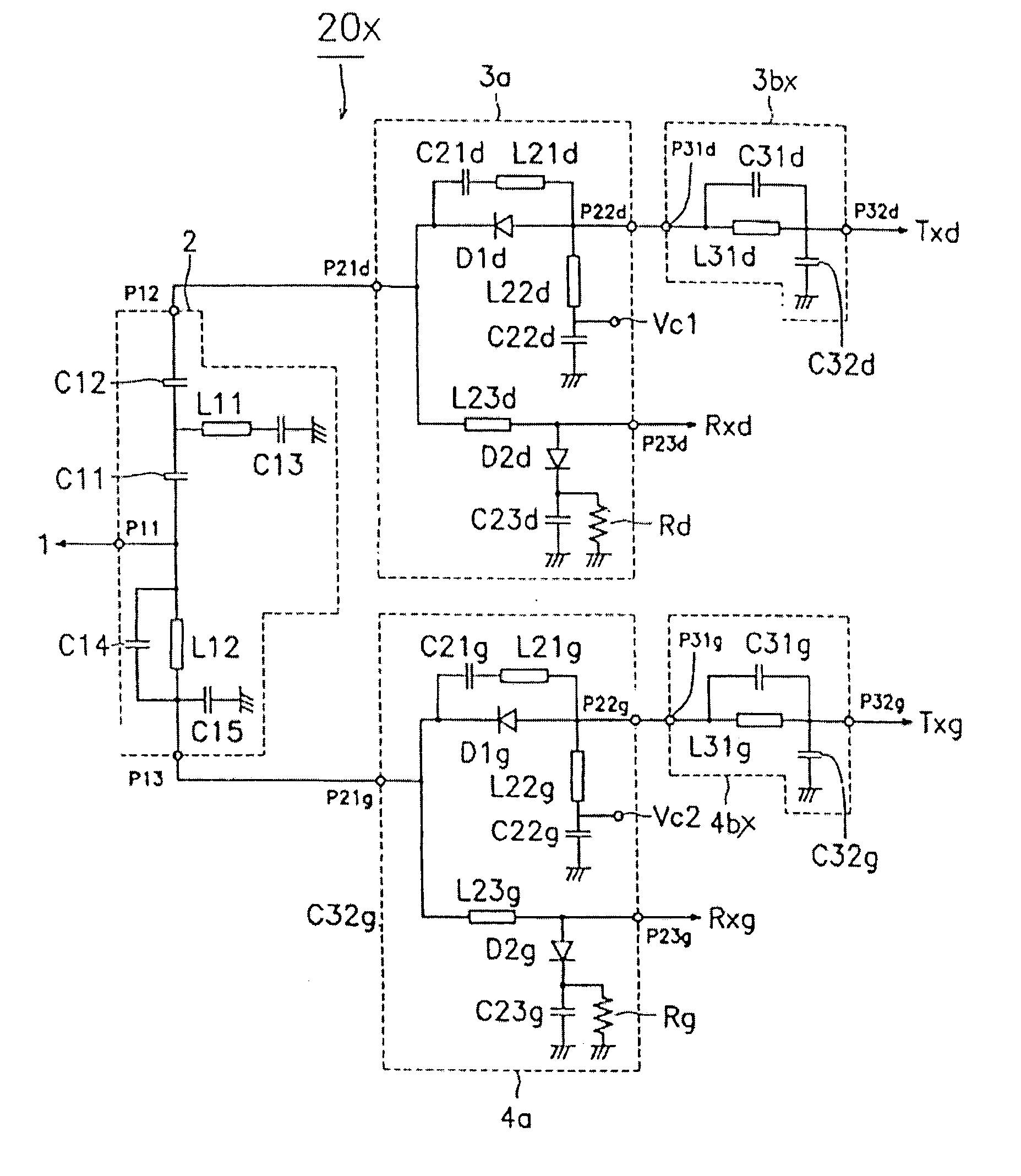
[0119]In the composite high frequency component of the above described second embodiment, each filter is connected to the transmission section side which is in the latter stage of the high frequency switch, the distortion during the transmission, caused by a high power amplifier provided in the transmission section can be attenuated by means of the filter. Thus, the insertion loss on the reception section side can be improved.

third embodiment

[0120]FIG. 6 is a circuit diagram of the composite high frequency component of the present invention. The composite high frequency component 30 is composed of the diplexer 2, a high frequency switch 31a and the notch filter 3b constituting the DCS system 3, and a high frequency switch 41a and the notch filter 4b constituting the GSM system 4.

[0121]The configurations of the diplexer 2, the notch filter 3b of the DCS system 3, and the notch filter 4b of the GSM system 4 are the same as those of the composite high frequency component 10 of the first embodiment of the FIG. 1.

[0122]The high frequency switch 31a (41a) is composed of the first and second diodes D1d (D1g) and D2d (D2g) which are first and second switching elements, the second inductors L21d through L23d (L21g through L23g) which are second inductance elements, and the second capacitors C21d through C23d (C21g through C23g) which are second capacitance elements. The second inductor L21d (L21g) is a parallel trap coil, and th...


PUM


Abstract

The invention provides a composite high frequency component constituting a part of a microwave circuit having plural signal paths corresponding to their respective frequencies, comprising: a diplexer for coupling transmitting signals from the plural signal paths for transmission and distributing receiving signals into said plural signal paths for reception; plural high frequency switches for separating the plural signal paths into a transmission section and a reception section, respectively; plural filters introduced in the signal paths; said diplexer, said high frequency switch, and said filters being integrated into a ceramic multi-layer substrate formed by lamination of plural ceramic sheet layers. According to the above described composite high frequency component, the diplexer, the high frequency switches, and the filters which constitute the composite high frequency component are integrated into the ceramic multi-layer substrate formed by lamination of plural ceramic sheet layers. Thus, the matching and adjustment between the diplexer and the high frequency switches can be easily performed. It is unnecessary to provide a matching circuit for matching and adjusting the diplexer and the high frequency switches, and moreover, the high frequency switches and the filters.

Description

[0001]This application is a Divisional of U.S. patent application Ser. No. 09 / 426,231 filed Oct. 22, 1999, now U.S. Pat. No. 6,633,748.BACKGROUND OF THE INVENTION[0002]1. Filed of the Invention[0003]The present invention relates to a composite high frequency component and a mobile communication device including the same, and more particularly to a composite high frequency component which can be used in plural different mobile communication systems and a mobile communication device including the same.[0004]2. Description of the Related Art[0005]At present, in Europe, as a mobile communication device, a dual band portable telephone has been proposed which can be operated in plural frequency bands, for example, DCS (Digital Cellular System) employing the 1.8 GHz band, and GSM (Global System for Mobile Communications) operative in the 900 MHZ band.[0006]FIG. 14 is a block diagram showing a part of the configuration of a dual band portable telephone as a conventional mobile communication...

Claims


Application Information

Patent Timeline
Patent Type & Authority Patents(United States)
IPC IPC(8): H04B1/40H03H7/46H04B1/48
CPCH03H7/46H03H7/463H04B1/005H04B1/0057H04B1/48H03H2001/0085H03H2250/00
Inventor WATANABE, TAKAHIROTANAKA, KOJIFURUTANI, KOJIMUTO, HIDEKIUEJIMA, TAKANORINAKAJIMA, NORIO
Owner MURATA MFG CO LTD
Learn More