
System for automatically locating and manipulating positions on an object

a technology applied in the field of automatic positioning and manipulating positions on objects, can solve the problems of lack of automatic positioning positions along objects, laborious task of identifying desired positions on objects in automated processes, and grids or tags on objects with or without grids or tags

Inactive Publication Date: 2007-04-03
TAFAS TRIANTAFYLLOS P +1
View PDF22 Cites 48 Cited by
  • Summary
  • Abstract
  • Description
  • Claims
  • Application Information

AI Technical Summary

Benefits of technology

This system significantly reduces the time spent reviewing biological material specimens under the microscope by enabling precise, automated location and identification of specimens, allowing for efficient specimen management and tracking.

Problems solved by technology

The identification of a desired position on an object in automated processes is often a laborious task.
From the foregoing it can be understood by those having ordinary skill in the art that although the systems and methods described above are adequate for locating objects themselves, they lack the capability of automatically locating positions along an object, with or without grids or tags on the object.

Method used


Image

  • System for automatically locating and manipulating positions on an object
  • System for automatically locating and manipulating positions on an object
  • System for automatically locating and manipulating positions on an object

Examples


Embodiment Construction

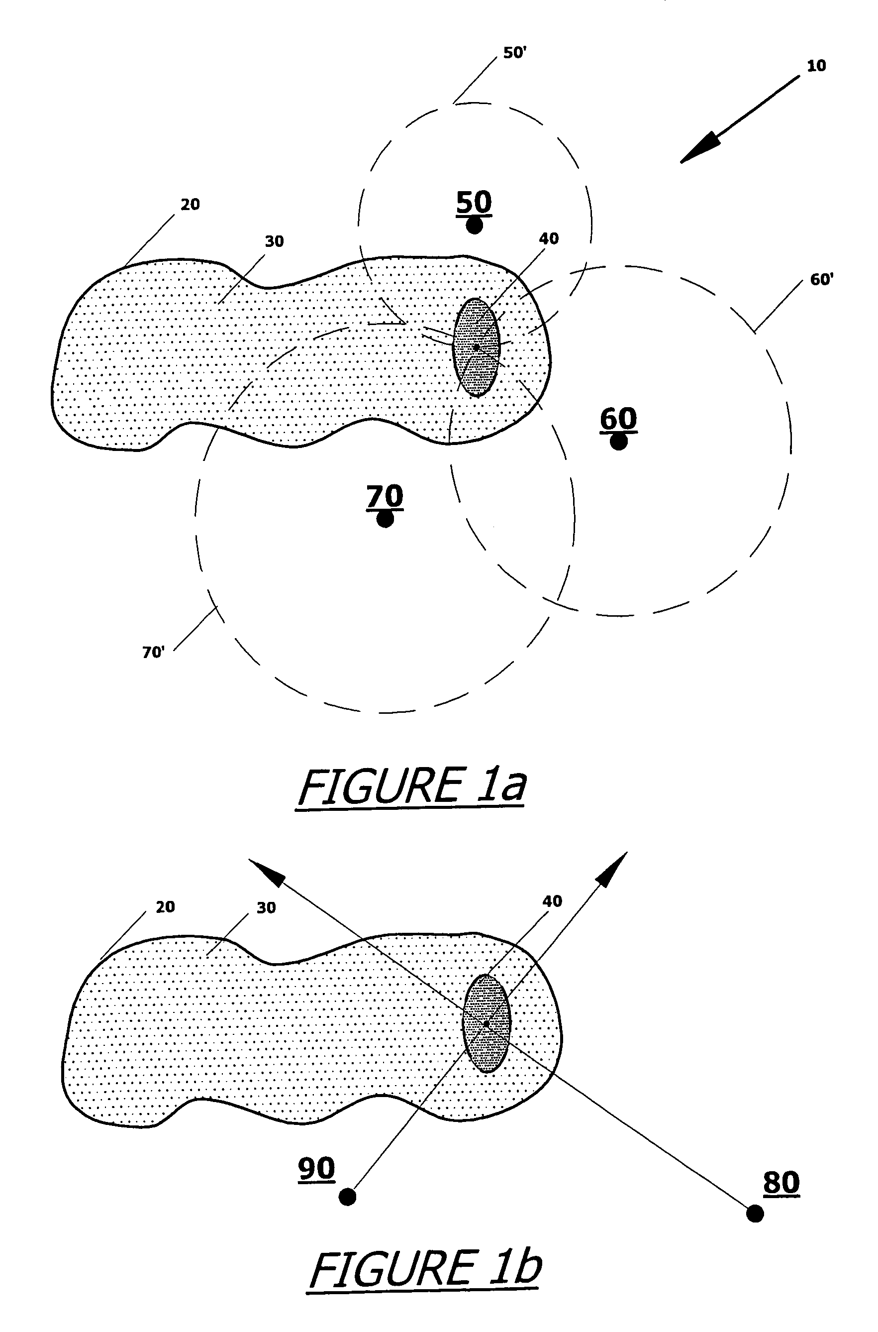
[0018]FIG. 1 shows an embodiment of a system 10 involving an assembly of components for locating an object 20 as well as any position or point 30 along or on the object. It will be understood that the object could be any animate or inanimate object having a body. Incorporated therein or thereon the object is a tag, preferably an electronic tag comprising a radio frequency identifier device (RFID). It is an aspect of the present invention that the tag is configured to operate cooperatively with an assembly of devices, such as 50, 60 and 70, positioned remotely as shown in FIG. 1. Each device is capable of sensing or reading the RFID and determining the position of the reading source (e.g., electromagnetic beam), on the object by use of the tag as a positional reference point. Then, using a method of triangulation, any point on the object can be determined precisely with the tag as a reference point, as described below.

[0019]Method of triangulation involves a process by which the loca...


PUM


Abstract

A system for automatically locating positions on an object and uniquely identifying the object employing an electronic tag positioned in or on the object. The system utilizes a plurality of sensors to locate the electronic tag and identify the object, and triangulation techniques to locate positions on the object where the object may be manipulated according to instructions coded with respect to the positions. Advantageously, the present invention may be used for automatically locating specimens on a microscope slide without regards to their positions on the slide, and for uniquely labeling a microscope slide.

Description

FIELD OF INVENTION[0001]This invention is related to a system and assembly for automatically locating positions along an object and for providing object identification. Advantageously, the present invention may be used for automatically locating specimens on a microscope slide without regards to their positions on the slide, and for uniquely labeling a microscope slide.BACKGROUND OF INVENTION[0002]The identification of a desired position on an object in automated processes is often a laborious task. Items in automated processes are typically placed in restrained area to allow for directed manipulation at desired positions of the objects based upon known dimensions of the object and knowledge of the position of predetermined reference points associated with the object. For example, numerous conventional microscope slides incorporate internal grids to locate a position on the microscope slides with respect to the viewing lens of a microscope. An external grid placed on the stage of th...

Claims


Application Information

Patent Timeline
Patent Type & Authority Patents(United States)
IPC IPC(8): G08B13/14G02B21/00G01S5/02G01S13/08G01S19/14G02B21/34G06V30/144G08B1/08
CPCB01L3/545G01N35/00732G01S5/02G02B21/34G02B21/365G06F19/366B01L2300/022B01L2300/0822G01N2001/282G01N2035/00782G01N2035/00851G16H10/40
Inventor TAFAS, TRIANTAFYLLOS P.KIM, YOUNGMIN
Owner TAFAS TRIANTAFYLLOS P
Learn More