
Method and apparatus for isolating RFI, EMI, and noise transients in power supply circuits

a power supply circuit and noise transient technology, applied in the field of electric circuits, can solve the problems of inconvenient operation, inability to meet the needs of users, and the noise of input line noise passing through to the output, so as to prevent the noise generated

Active Publication Date: 2007-03-27
GABRIEL PATENT TECH
View PDF12 Cites 19 Cited by
  • Summary
  • Abstract
  • Description
  • Claims
  • Application Information

AI Technical Summary

Benefits of technology

[0015]The inventive circuit provides near 100% isolation and immunity to power line transmitted noise, transients, RFI and EMI. The inventive circuit eliminates the need for filter coils and high frequency filter capacitors often required for noise reduction in conventional linear power supply designs. The inventive circuit eliminates both common-mode and differential-mode power line noise from entering the power supply. Additionally, the inventive circuit prevents noise generated by the output load circuitry from being “kicked back” onto the DC input or AC power line.

Problems solved by technology

However, they may not be suitable when the primary requirement for the power supply is low noise.
When the switched-mode rectifiers are in a conduction state and the switching transistor is on, input line noise may pass through to the output.
Additionally, the line-connected rectifiers generate significant power harmonics that are kicked-back onto the power line.
However, the purpose of synchronous rectifiers is to convert voltage, while the purpose of the inventive circuit is noise and interference isolation.

Method used


Image

  • Method and apparatus for isolating RFI, EMI, and noise transients in power supply circuits
  • Method and apparatus for isolating RFI, EMI, and noise transients in power supply circuits
  • Method and apparatus for isolating RFI, EMI, and noise transients in power supply circuits

Examples


Embodiment Construction

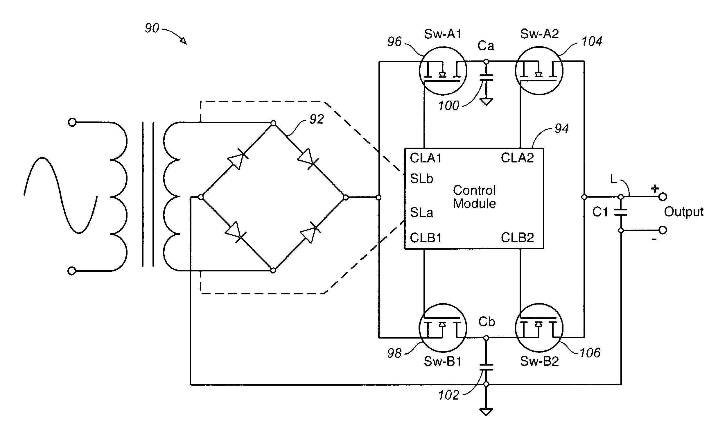
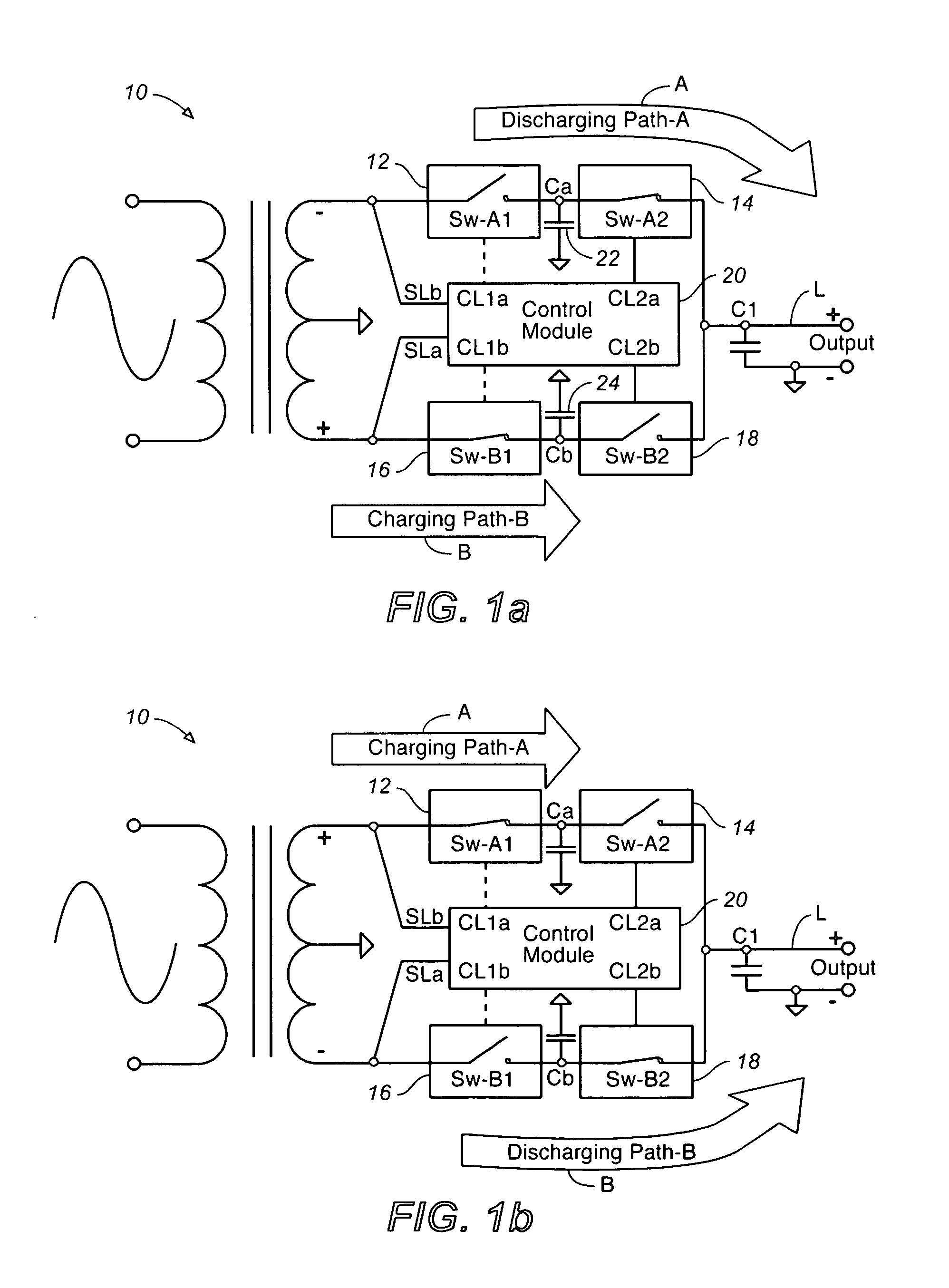
[0020]FIGS. 1a and 1b are schematic views of a power supply circuit of this invention in a linear fullwave power supply 10. In operation, the switches 12, 14, 16, and 18 are controlled by the control module 20 in such a manner that current path A is charged by the input voltage, while current path B provides current to the circuit output or load L, and vice versa: as the stored power level of path A begins to drop, the control module 20“gates” the switches allowing current path A to charge, while the fully charged path B provides current to the output.

[0021]During the charge cycle of path A (FIG. 1b), path A's second (post-storage) switch 14 is open, blocking transients and noise from the AC input to the output. Simultaneously, path B's second (post-storage) switch 18 is closed, supplying current to the output load L, while path B's first switch (pre-storage) 16 is in an off condition, blocking AC input transients and noise to the output.

[0022]Conversely, during the charge cycle of ...


PUM


Abstract

A method and apparatus for isolating and / or eliminating RFI, EMI, and noise transients in power supply circuits. The circuit isolates DC to DC and AC to DC power coupling by use of dual, parallel current paths that are alternately gated. The gating of the switches is controlled by a control module, which ensures that the input and output of the circuit is electromagnetically blocked during any instant in time, while simultaneously ensuring proper and continuous delivery of current to the circuit output load.

Description

CROSS-REFERENCES TO RELATED APPLICATIONS[0001]This application claims the benefit of U.S. Provisional Application Ser. No. 60 / 371,614, filed Apr. 10, 2002.STATEMENT REGARDING FEDERALLY SPONSORED RESEARCH OR DEVELOPMENT[0002]Not applicable.REFERENCE TO A MICROFICHE APPENDIX[0003]Not applicable.BACKGROUND OF THE INVENTION[0004]1. Field of the Invention[0005]The present invention relates generally to electrical circuits, and more specifically to an improved method and associated power supply circuit that provides circuit protection from AC line noise, transient electromagnetic interference, EMI, and RFI.[0006]2. Discussion of the Related Art Including Information Disclose under 37 CFT 1.97 and 37 CFR 1.98[0007]Switched-mode power supplies make use of power transistors or power MOSFETs and typically require the use of a control module. However, the purpose and operation of the semi-conductor switches and of the control module are entirely different from that in the present invention. Th...

Claims


Application Information

Patent Timeline
IPC IPC(8): H02H9/00H02M1/12H02M1/15H02M1/44H02M3/158H02M7/217
CPCH02M1/12H02M1/15H02M7/217H02M3/158H02M1/44
Inventor GABRIEL, CAELIN
Owner GABRIEL PATENT TECH
Learn More