
Filters

a filter and filter body technology, applied in the field of filters, can solve the problems of many problems associated with conventional filters, high cost of many fluids, and damage to micro-electronic components being fabricated,

Inactive Publication Date: 2007-03-27
PALL CORP
View PDF458 Cites 32 Cited by
  • Summary
  • Abstract
  • Description
  • Claims
  • Application Information

AI Technical Summary

Benefits of technology

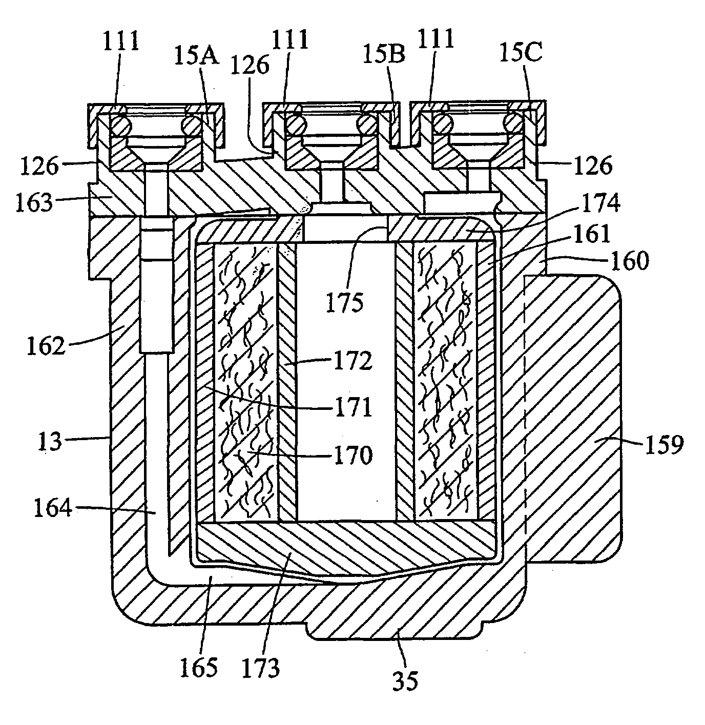
[0009]In accordance with another aspect of the invention, a filter comprises a filter cartridge and a housing. The filter cartridge includes a filter element having non-radially extending pleats. The height of each pleat is greater than (D−d) / 2 and is less than or equal to (D2−d2) / [4(d+2t)], where D and d are the outside and inside diameters, respectively, of the pleated filter element at the crests and roots of the pleats and t is the thickness of a pleat leg. The housing is fitted around the filter cartridge and has an inlet and an outlet defining a fluid flow path. The filter cartridge is disposed in the housing in the fluid flow path and the housing and the filter cartridge are arranged to reduce hold up volume and dead zones in the fluid flow path.

Problems solved by technology

Many fluids, such as photo-resist liquids used in the micro-electronics industry, are exceedingly expensive.
These liquids must be filtered immediately prior to being used or impurities in the liquids can damage the micro-electronic components being fabricated.
Conventional filters have many problems associated with them.
These hold up volumes are expensive because the expensive liquid trapped in the hold up volumes is discarded when the filter is discarded.
Further, many of these filters have dead zones where the flow of fluid stagnates.
When a liquid such as a photo-resist liquid stagnates it can undergo chemical and / or physical changes which can be detrimental to the fabrication process.
In addition, when the liquid is first pumped through a filter having large hold up volumes and dead zones, the amount of time and the amount of wasted liquid required to fill the hold up volumes and the dead zones before a clean filtered liquid emerges from the outlet of the filter can be considerable.

Method used


Image

  • Filters
  • Filters
  • Filters

Examples


example 1

[0160]A test system 300 shown in FIG. 64 is used to evaluate liquid displacement in a first filter, a second filter, and a third filter as a dispense liquid is dispensed through the filters. The test system 300 includes a dispense liquid container 301, a dispense pump 302, a housing 303, a drawback 304, a container 305 on a balance or scale 306, and electronics 307, such as a PC, coupled to the scale 306. The first filter, which is similar to the capsule filter 310 shown in FIG. 65 but utilizes the bowl 311 shown in FIG. 66, has a filtration area of 660 cm2 and a hold up volume of 42 cc. The second filter, which is similar to the capsule filter 312 shown in FIG. 67 but utilizes the bowl 313 shown in FIG. 68, also has a filtration area of 660 cm2 and a hold up volume of 42 cc. The third filter, which is similar to the capsule filter 314 shown in FIG. 69, has a filtration area of 2800 cm2 and a hold up volume of 130 cc. The hold up volume of each filter is the inner volume of the filt...

example 2

[0180]A test system 320 shown in FIG. 76 is used to determine bubble and particle counts downstream of the first filter, second filter and third filter of Example 1. The test system includes a source 321 of air, a pressure tank 322, a pressure guage 323, the test filter 324, a particle counter 325 (e.g., a RION KS-16F), and a flow meter 326. The test liquid is the hexyleneglycol of Example 1.

[0181]The test procedure is as follows:[0182](1) the test liquid is loaded into the tubing and the test filter;[0183](2) after venting, the liquid is passed through the test filter to the particle counter, which is started simultaneously just after venting, and[0184](3) the bubble and particle counts for bubbles / particles greater than 0.1 and 0.2 micron were measured as a function of time at a 10 mL / min flow rate.

[0185]As shown in FIG. 77, the first and second filters showed a quick drop for the downstream particles. The first and second filters have a smaller filtration area than the third filt...


PUM

PropertyMeasurementUnit
Fractionaaaaaaaaaa
Fractionaaaaaaaaaa
Lengthaaaaaaaaaa

Abstract

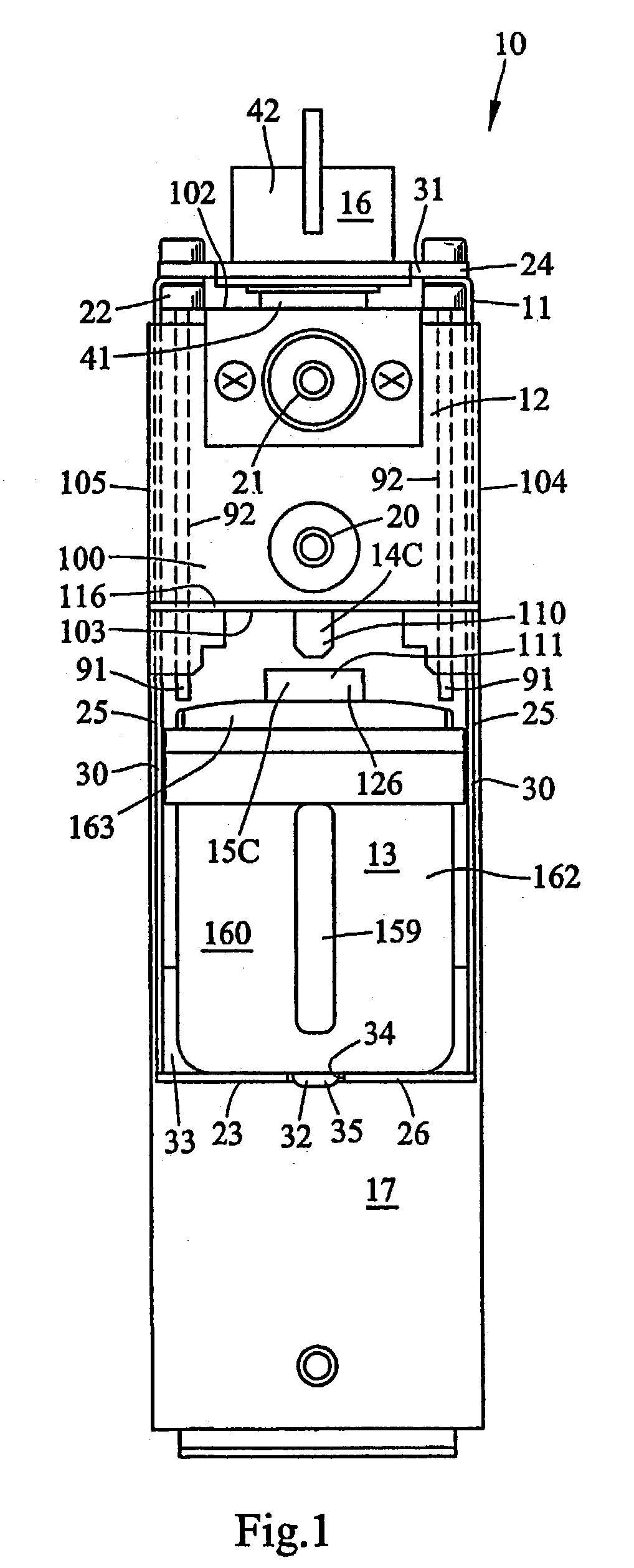
A filter comprising a filter cartridge and a housing having at least one fitting and defining a chamber, the filter cartridge being disposed in the chamber, wherein the housing includes a fluid conduit which extends axially from the fitting along the periphery of the filter cartridge, the fluid conduit being isolated from the filter cartridge chamber along a substantial portion of the length of the fluid conduit.

Description

[0001]This application claims priority based on U.S. Provisional Application No. 60 / 203,948, filed May 12, 2000 and U.S. Provisional Application No. 60 / 216,697, filed Jul. 7, 2000, both of which are incorporated by reference.TECHNICAL FIELD[0002]The present invention relates to filters which may be used in a wide variety of applications including, for example, the filtration of a photo-resist liquid.BACKGROUND OF THE INVENTION[0003]Many fluids, such as photo-resist liquids used in the micro-electronics industry, are exceedingly expensive. These liquids must be filtered immediately prior to being used or impurities in the liquids can damage the micro-electronic components being fabricated.[0004]Conventional filters have many problems associated with them. For example, many conventional filters have relatively large volumes within them, e.g., hold up volumes, which collect and trap the liquid. These hold up volumes are expensive because the expensive liquid trapped in the hold up volu...

Claims


Application Information

Patent Timeline
IPC IPC(8): B01D27/06B01D27/08B01D35/01B01D29/11B01D29/15B01D29/21B01D35/30B01D36/00
CPCB01D27/08B01D29/15B01D29/21B01D35/30B01D36/001B01D29/902B01D29/96B01D29/601B01D2201/4046B01D2201/4023B01D2201/4015B01D2201/40B01D2201/34B01D2201/301
Inventor HIRANAGA, HAJIMEHOSHINO, TATSUYA
Owner PALL CORP
Learn More