
Collaborative pointing devices

Inactive Publication Date: 2007-03-20
YORK UNIVERSITY
View PDF15 Cites 64 Cited by
  • Summary
  • Abstract
  • Description
  • Claims
  • Application Information

AI Technical Summary

Benefits of technology

[0025]Advantageously, the controller causes said laser beam to be emitted for less than 0.25 seconds, thus making the laser pointers eye-safe. Also, as a further preference, if the laser spot is not detected in a predetermined number of successive captured images, the laser beam is turned off by the controller thereby preventing eye damage by said laser beam.

Problems solved by technology

Traditionally, most hardware platforms for SDG support only one person interacting at any given time, which limits collaboration, and so when multiple users want to use a computer collaboratively, they are currently forced to take turns to control the system.
If there is only one interaction device that is wired to the computer, the device can only be used in a limited range.
Even worse, since there is only one input device available, participants are forced to go through the process of acquiring the device before they can contribute their ideas.
A drawback of this scheme is that there is a need for accountability for each participant's actions; therefore each pointing device must be tracked in order to uniquely identify same.
However, this proposed solution fails when multiple laser spots come in close proximity.
Also, it is particularly difficult to reliably attribute the laser spots different laser pointers, since the laser pointer may have left the screen or turned off by the user.
However, laser pointers outside the 650–680 nm range are relatively expensive, and bright laser spots often saturate the image sensors or CCDs of the camera, and thus it is relatively hard to reliably detect the color of a laser pointer from the image.

Method used


Image

  • Collaborative pointing devices
  • Collaborative pointing devices
  • Collaborative pointing devices

Examples


Embodiment Construction

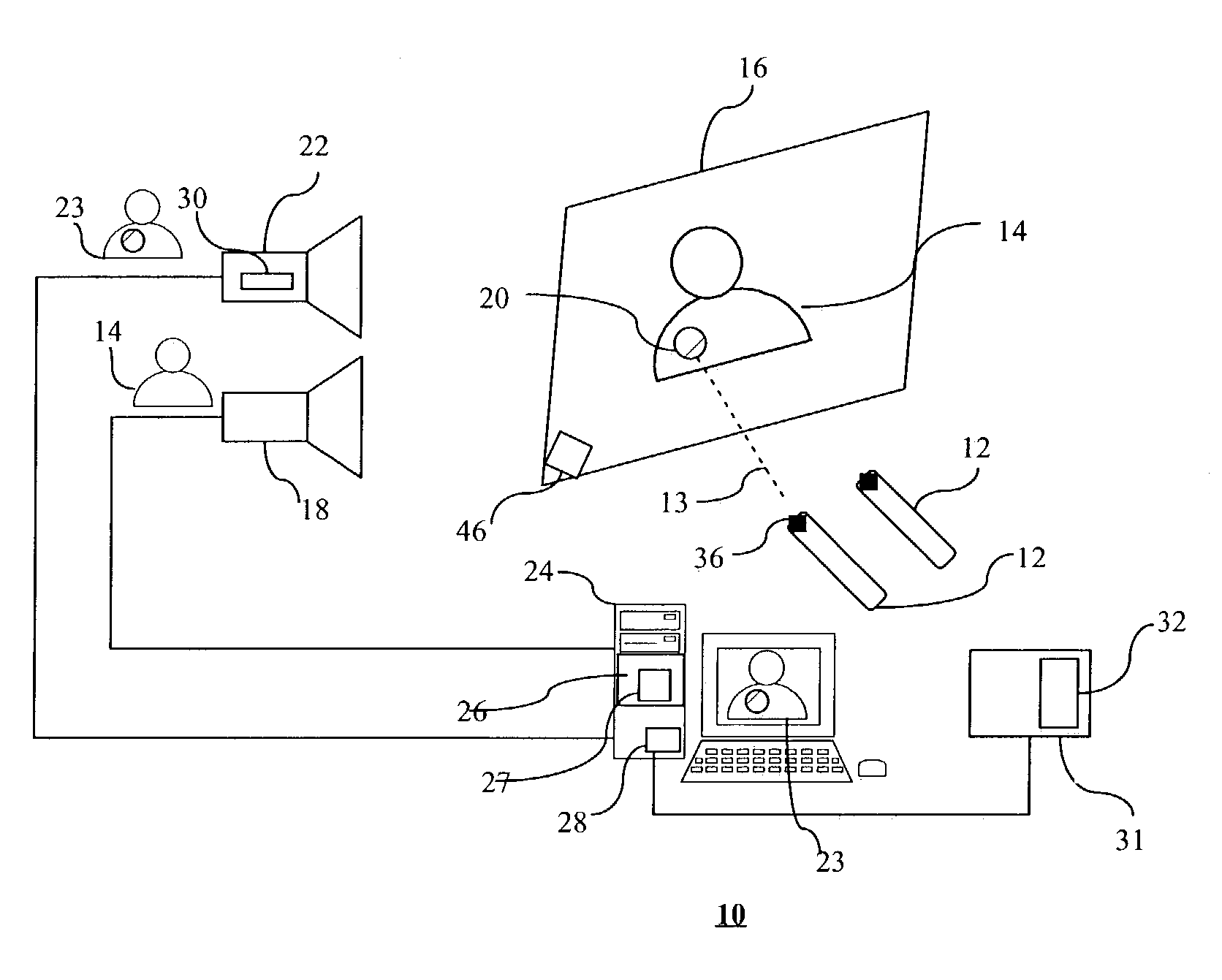
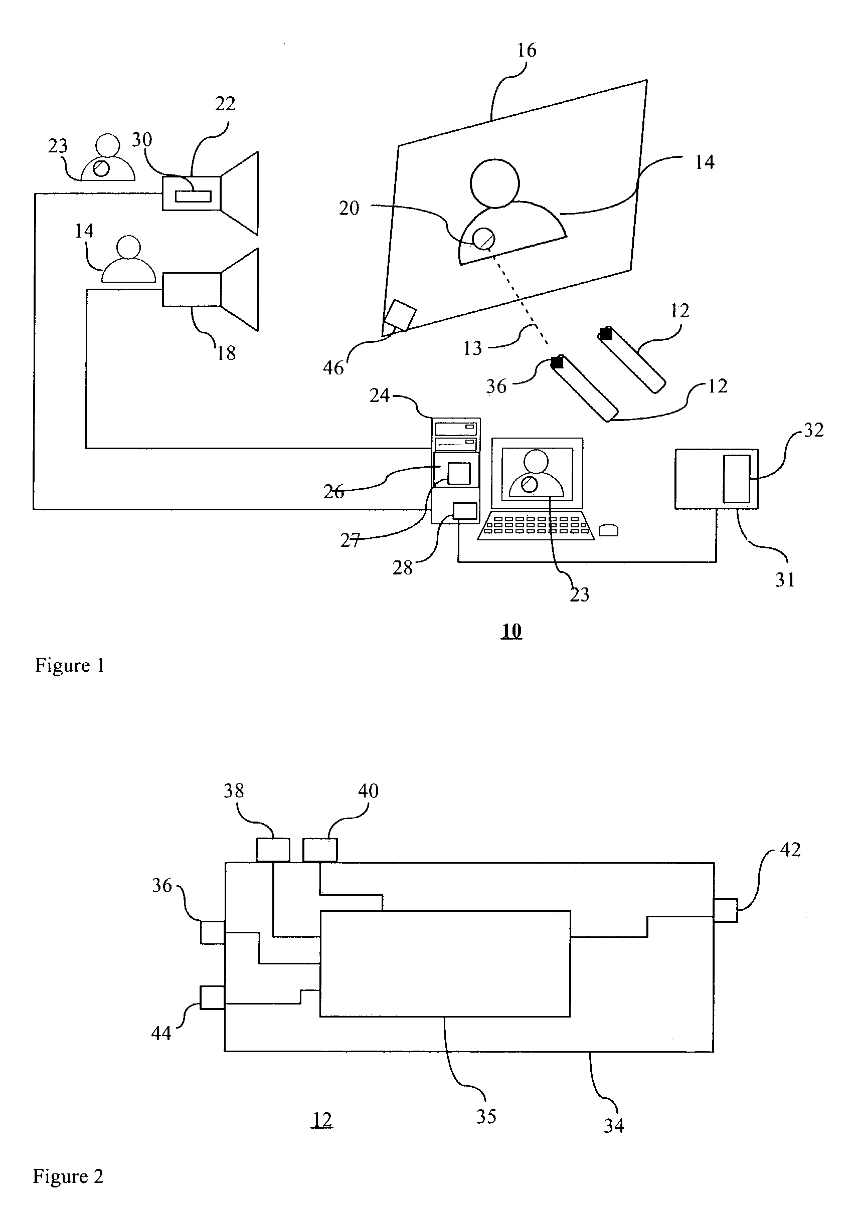
[0033]Reference is first made to FIG. 1, which is an overview of a system 10 for implementing a method for allowing a plurality of input devices 12 to interact with a displayed image 14 on a screen or display 16. The image 14 is projected onto the display 16 by an image projector 18. Generally, the input devices 12 are laser pointers which include a laser that is relatively safe to users, such as a Class III A type laser. Each laser pointer 12 is caused to emit directional visible light or a laser beam 13 onto the display 16, which produces a visually recognizable laser spot 20 on the display 16.

[0034]The system 10 also includes a camera 22 for capturing successive images 14 on the display 16, to form captured images 23 thereof. The laser pointers 12, display 16 and projector 18, are coupled to a computer 24 which processes the captured images 23, and determines locations of laser spots 20 due to each laser pointer 12.

[0035]The computer 24 includes a processor 26 which receives capt...


PUM


Abstract

A method and system for determining a position of laser spots in an initial image due to a plurality of laser pointer, the method having the steps of acquiring a sequence of images from a camera directed at the initial image to produce acquired images thereof, each said acquired image comprising image elements forming a frame; assigning each of said laser pointers a unique transmission pattern; registering said code of each of said laser pointers during frame i with a processor; determining said laser spots in said frame i; registering the appearance of the laser spots of each of the laser pointers during frame i with a processor; assigning positional coordinates to each said located laser spots so as to produce a sequence of positional coordinates (xi,yi) corresponding to sequential positions of the laser spot in the initial image; whereby said laser spots appear in the captured images in a pattern corresponding to said unique transmission pattern and each of said laser pointers is uniquely identifiable and tracked.

Description

BACKGROUND OF THE INVENTION[0001]1. Field of the Invention[0002]The present invention relates in general to collaborative pointing devices, more specifically it relates to laser pointers.[0003]2. Description of the Prior Art[0004]Single Display Groupware (SDG) is defined as a system that can support collaborative work between people that are physically in relative proximity, such as in the same room. Since users are sharing a display in the same room, they are free to interact face to face, which facilitates collaboration. General computer systems are designed to support interaction with only one user at a time. Traditionally, most hardware platforms for SDG support only one person interacting at any given time, which limits collaboration, and so when multiple users want to use a computer collaboratively, they are currently forced to take turns to control the system. If there is only one interaction device that is wired to the computer, the device can only be used in a limited range...

Claims


Application Information

Patent Timeline
IPC IPC(8): G09G5/08G06F3/0354G06F3/042
CPCG06F3/0386G06F3/038
Inventor STUERZLINGER, WOLFGANG
Owner YORK UNIVERSITY
Learn More