Suspended centrifugal pouring machine unloading device and unloading method
A technology of centrifugal pouring and unloading device, which is applied in the field of unloading device and unloading, which can solve the problems of high physical endurance requirements of staff, reduce equipment processing efficiency, increase production cost of enterprises, etc., so as to avoid human eye injury, Reduce the frequency of replacement and achieve the effect of safe production
- Summary
- Abstract
- Description
- Claims
- Application Information
AI Technical Summary
Problems solved by technology
Method used
Image
Examples
Embodiment 1
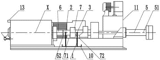
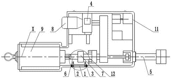
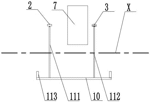
[0033] A hanging type centrifugal pouring machine unloading device disclosed in this embodiment, as attached figure 2 As shown, it includes a suspended centrifugal pouring machine 11, and the suspended centrifugal pouring machine 11 includes a discharge port, a push rod 5, a hydraulic cylinder 8 that drives the push rod 5 to reciprocate, and a control that controls the operation of the hydraulic cylinder 8. device 4.
[0034] The discharge port is located at one end of the suspended centrifugal casting machine 11 in the X-axis direction, the processed cylinder ring casting 9 is located in the discharge port, and a baffle is also arranged at the exit of the discharge port; The initial end 51 of the push rod 5 is located outside the other end of the suspended centrifugal pouring machine 11 in the X-axis direction, and the extension end 52 of the push rod 5 is connected to the transmission shaft 6 through a quick-change joint. The push rod 5 enters or exits the discharge port d...
Embodiment 2
[0055] The overall structure of this embodiment is similar to that of Embodiment 1, the difference is that: Figure 5 As shown, the stroke adjustment bracket 1 includes a flat plate 15, the flat plate 15 is set on the suspended centrifugal pouring machine 11 through at least one support frame, and the flat plate 15 is provided with a chute 16 of a specified length in the X-axis direction , the length of the chute 16 is consistent with the length of the chute on the bottom plate 10 in Embodiment 1, the feed termination contact 2 and the withdrawal termination contact 3 can be slidably arranged on the chute, the The flat plate 15 is provided with a scale line 17, according to the scale line 17, by manually sliding the feed stop contact 2 and the retreat stop contact 3, the precise adjustment of the distance between them can be realized.
[0056] The working process of this implementation is similar to the process of embodiment 1, the difference is that: the adjustment process of...
PUM
 Abstract
Description
Claims
Application Information
 - R&D
- Intellectual Property
- Life Sciences
- Materials
- Tech Scout
- Unparalleled Data Quality
- Higher Quality Content
- 60% Fewer Hallucinations
Browse by: Latest US Patents, China's latest patents, Technical Efficacy Thesaurus, Application Domain, Technology Topic, Popular Technical Reports.
© 2025 PatSnap. All rights reserved.Legal|Privacy policy|Modern Slavery Act Transparency Statement|Sitemap|About US| Contact US: help@patsnap.com


