Machine head structure of jewelry processing machine

A jewelry processing and machine head technology, applied in clothing, application, jewelry and other directions, can solve the problems of gold and silver jewelry processing errors, fixed or just moving up and down, large metal loss, etc., to achieve multi-processing angles, multi-directional adjustment , the effect of reducing errors

Pending Publication Date: 2021-10-26
吴业伟
View PDF1 Cites 0 Cited by
  • Summary
  • Abstract
  • Description
  • Claims
  • Application Information

AI Technical Summary

Problems solved by technology

[0002] Gold and silver jewelry is a very common ornament in people's daily life. The traditional technology of processing gold and silver jewelry is all manual work. This operation method has low production efficiency and large metal loss. In the prior art, mechanical equipment is generally used. To process gold and silver jewelry, the machine head drives the tool to process the gold and silver jewelry. However, in the prior art, the machine head is usually fixed or only moves up and down. Usually, the jewelry is fixed and processed by a fixture, and the angle and rotation are also By re-changing the direction of the jewelry and clamping it to realize the processing of gold and silver jewelry from other angles, even experienced old staff will cause certain errors in the processing of gold and silver jewelry, which not only affects its aesthetics, and cost loss
The document of prior art publication number CN206392982U provides a head structure of a jewelry processing machine. This device has the following problems: the device only realizes the movement in the horizontal direction, but cannot process jewelry in other angle directions, so it is necessary to rework the jewelry. Change the direction of clamping to realize the processing of gold and silver jewelry from other angles. Even experienced old staff will cause certain errors in the processing of gold and silver jewelry, which not only affects its aesthetics, but also causes cost losses.

Method used


Image

  • Machine head structure of jewelry processing machine
  • Machine head structure of jewelry processing machine
  • Machine head structure of jewelry processing machine

Examples


Embodiment Construction

[0028] see Figure 1-8 , the present invention provides a kind of technical scheme:

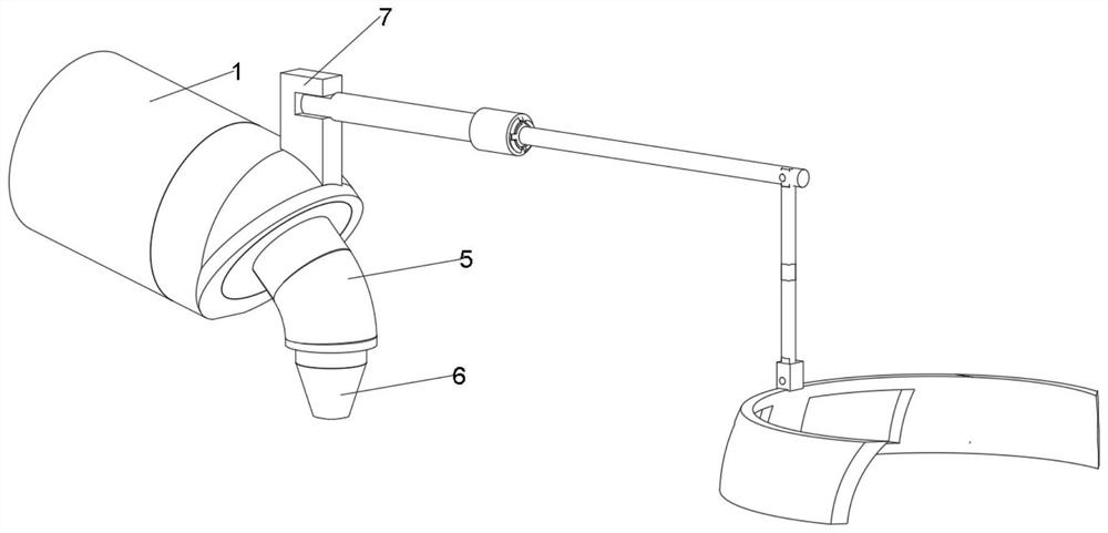
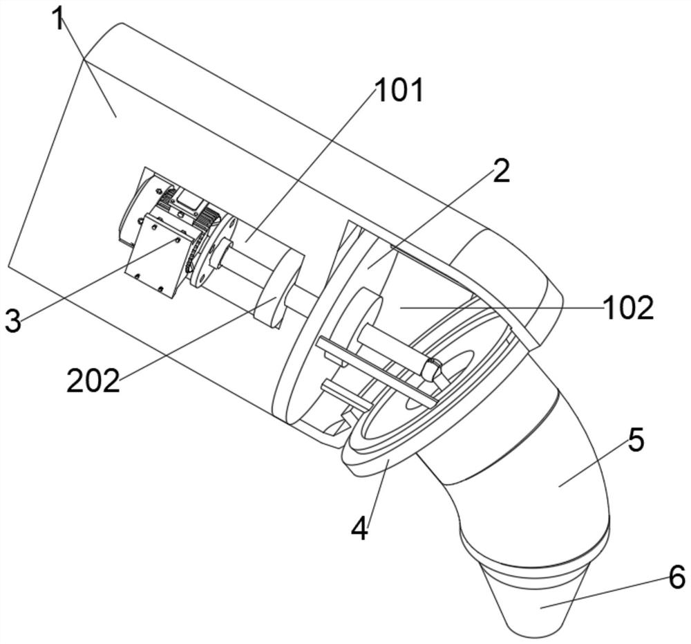
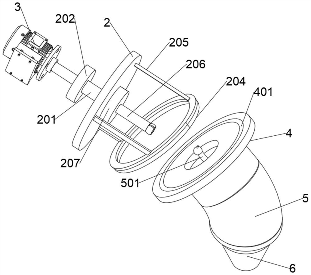
[0029]A head structure of a jewelry processing machine, comprising a columnar block 1, an organic cavity 101 is provided on the rear side of the columnar block 1, a cavity 102 is provided on the front side of the columnar block 1, a turntable 2 is arranged inside the cavity 102, and a turntable 2 There is a sleeve A201 in the middle of the rear side, the rear end of the sleeve A201 extends through the inner wall of the cavity 102 to the inside of the machine cavity 101 and is sleeved with the limit box A202, the front side of the turntable 2 is provided with a circular track 204, and the rear side of the circular track 204 A plurality of support rods 205 are fixed at equal intervals in a ring shape, a sleeve B206 is provided in the middle of the front side of the turntable 2, the rear end of the sleeve B206 is sleeved with a limit box B207, and the front end of the sleeve B206 is provided wit...


PUM


Abstract

The invention discloses a machine head structure of a jewelry processing machine, and belongs to the technical field of jewelry processing machines. The machine head structure of the jewelry processing machine comprises a cylindrical block, a rotating disc is arranged in a cavity, a sleeve A is arranged in the middle of the rear side of the rotating disc, an annular rail is arranged on the front side of the rotating disc, a plurality of supporting rods are annularly and fixedly arranged on the rear side of the annular rail at equal intervals, a sleeve B is arranged in the middle of the front side of the rotating disc, the middle of the front side of the adjusting disc is provided with a connecting block, and the middle of the rear side of the connecting block is fixedly provided with a fixing column; and the machine head main body is arranged at the lower end of the connecting block, and the structures are tightly matched so that the machine head with the structure can be adjusted in the side direction and angle, the processing of most gold and silver jewelry is met, the processing technology can be continuously carried out, and the problem that the jewelry cannot be processed in other angle directions is effectively avoided. Therefore, the jewelry needs to be clamped in different directions to realize the processing of the gold and silver jewelry from other angles so that the processing error of the gold and silver jewelry is reduced, and the gold and silver jewelry is more attractive.

Description

technical field [0001] The invention relates to the technical field of jewelry processing machines, and more specifically, relates to a head structure of a jewelry processing machine. Background technique [0002] Gold and silver jewelry is a very common ornament in people's daily life. The traditional technology of processing gold and silver jewelry is all manual work. This operation method has low production efficiency and large metal loss. In the prior art, mechanical equipment is generally used. To process gold and silver jewelry, the machine head drives the tool to process the gold and silver jewelry. However, in the prior art, the machine head is usually fixed or only moves up and down. Usually, the jewelry is fixed and processed by a fixture, and the angle and rotation are also By re-changing the direction of the jewelry and clamping it to realize the processing of gold and silver jewelry from other angles, even experienced old staff will cause certain errors in the p...

Claims


Application Information

Patent Timeline
IPC IPC(8): A44C27/00
CPCA44C27/00
Inventor 吴业伟
Owner 吴业伟
Why Eureka
Try Eureka