
Device and method for vascular monitoring

Inactive Publication Date: 2007-03-20
SYNOVIS LIFE TECH
View PDF20 Cites 113 Cited by
  • Summary
  • Abstract
  • Description
  • Claims
  • Application Information

AI Technical Summary

Benefits of technology

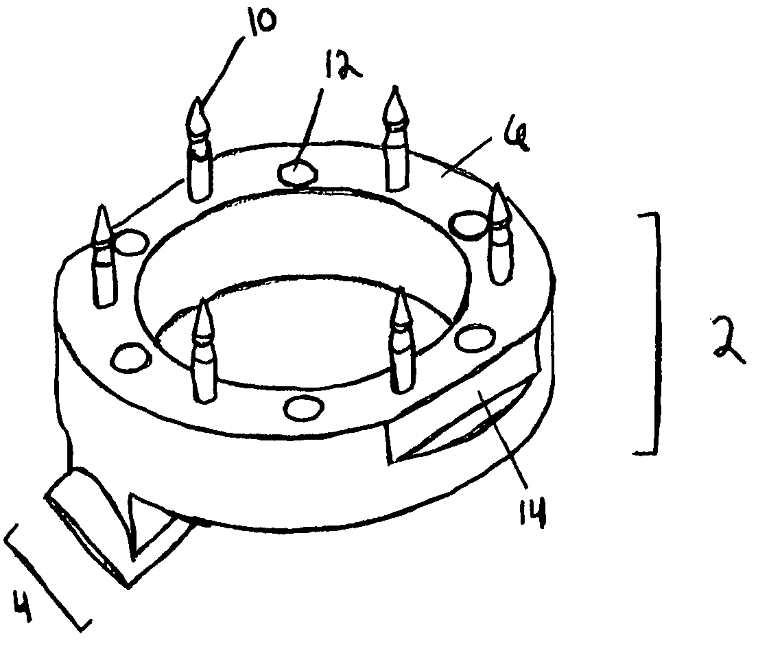
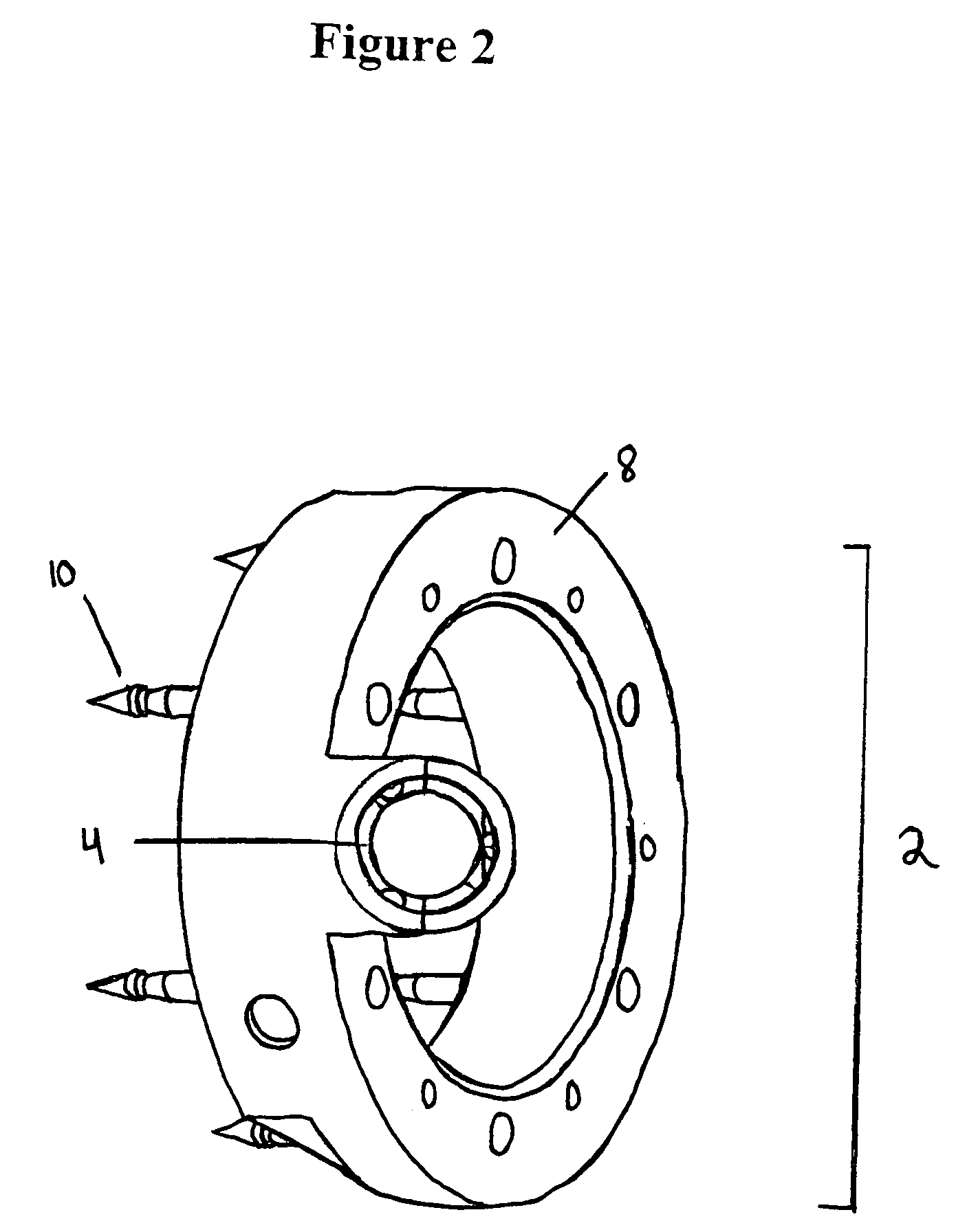
[0029]A preferred anastomotic coupler of this type generally comprises two identical fastener portions adapted to be connected together by the surgeon and under microscopic visualization in order to join abutting vascular portions. The fastener portions can be preloaded into a delivery device, adapted to connect the portions in situ in order to provide a secure anastomotic attachment. Either or both of the fastener portions are adapted to receive a corresponding sensing device, as in the form of a Doppler probe releasably positioned upon a suitable delivery instrument. The use of identical portions in this manner, provides the surgeon with the option to use either or both portions for the placement of a sensing device, and facilitates both the manufacture and use of the coupler itself.
[0031]In a preferred embodiment, for instance, the sensing device comprises a conventional Doppler probe which can be used ‘as is’ or is preferably suitably modified (e.g., dimensioned and / or shaped) to permit it to be mated within a receptacle of a fastener portion in order to form a combination device of this invention. A receptacle can be adapted to position the sensing device upon the coupler, and in turn with respect to the vessel, in any suitable orientation and manner. In a particularly preferred embodiment, the receptacle and probe are configured in a manner that facilitates both the initial placement of the probe in the receptacle, e.g, using an insertion tool as described herein, as well as the later removal of the probe from the receptacle (e.g., by the use of minimal pulling forces), and in turn, from the body itself.

Problems solved by technology

While free flap surgeries have a history of success, highly undesirable consequences of a flap failure still remain a possibility.
One of the main causes of flap failure is a lack of blood being supplied to the flap tissue.
When not enough blood is supplied to the flap tissue, tissue necrosis results.
However, if it can be recognized early enough that the flap is not receiving adequate circulation, it may be saved, or salvaged.
Unfortunately, devices such as that described above continue to suffer from various drawbacks, including in particular the fact that the probe itself is in an approximate position that is less than optimal (approximately 90 degrees to the flow of blood).
Moreover, the position of both the cuff, and in turn the probe itself, is unpredictable and itself subject to change, e.g., as the cuff moves along and / or around the vessel, or even when the patient himself changes positions.
It can be seen, therefore, that while Doppler probes are helpful in blood flow monitoring, they suffer from several drawbacks.
One drawback with implanted probes arises in the present inability to reliably and stably position the probe either within or about a vessel.
Surgeons often report difficulties in positioning the probe because they must manually position the probe about the vessel with their hands or with forceps.
Positioning the probe is also problematic because of the restricted space in the body in which the surgeon has to work.
These problems of positioning also increase the risk that the probe would be accidentally detached from the blood vessel and lost in the body.

Method used


Image

  • Device and method for vascular monitoring
  • Device and method for vascular monitoring
  • Device and method for vascular monitoring

Examples


Embodiment Construction

[0035]The invention further provides a method of preparing and a method of using a coupler and sensing device combination of the type disclosed, including a system that includes either a coupler and / or sensing device adapted to be positioned together, as well as various other components, such as an insertion tool adapted to position the sensing device within the coupler.

[0036]The predictable, and predetermined orientation of a sensing device, as permitted by the combination device, permits a variety of new methods and opportunities in the course of its use. For instance, in a particularly preferred embodiment, a combination of this invention is particularly well suited to permit the Doppler sensing device to perform a technique referred to herein as “flow / velocity trend analysis”, in which various aspects concerning blood flow within a vessel can be monitored and recorded in order to provide a baseline for objective comparison with later-collected data. That baseline can be provided...


PUM


Abstract

A vascular coupler adapted to be fixed into position upon a blood vessel and there retain and position a matable sensing device. In a preferred embodiment, the vascular coupler is an anastomotic coupler and the sensing device comprises an ultrasonic Doppler probe.

Description

FIELD OF THE INVENTION[0001]This invention relates generally to medical devices, and more particularly to devices for monitoring parameters such as blood flow in a blood vessel during or after a surgical procedure. In another aspect, the invention relates to medical devices that can be attached to vessels within the body, including anastomotic devices for the secure attachment of vessel portions to each other.BACKGROUND OF THE INVENTION[0002]Over the last decades, many advances have been made in the area of microvascular surgery, particularly in the area of free flap tissue surgery. Free flaps are regularly used in plastic and reconstructive surgery, for example in breast reconstruction. In free flap surgery, tissue and / or muscle is removed from one part of the body, along with an associated artery and vein, and is reattached to another part of the body. The artery and vein of the transferred tissue and / or muscle are then anastomosed (that is, connected) to a native artery and vein ...

Claims


Application Information

Patent Timeline
IPC IPC(8): A61B5/00A61B5/02A61B8/06A61B8/08A61B17/00
CPCA61B8/06A61B8/12A61B17/11A61B8/08A61B2017/1107A61B8/488A61B2017/00022A61B8/4472
Inventor CAMPBELL, MICHAEL K.KUESTER, III, WILLIAM F.MOORADIAN, DANIEL L.
Owner SYNOVIS LIFE TECH
Learn More