Support base for toolholder of a milling drum

Inactive Publication Date: 2007-03-20
CATERPILLAR PAVING PROD INC
View PDF19 Cites 11 Cited by
  • Summary
  • Abstract
  • Description
  • Claims
  • Application Information

AI Technical Summary

Benefits of technology

[0007]In accordance with the present invention an easy and quick replacement of tools on a milling drum is facilitated by constructing the required support base and the support portion associated with respective tools more compact without compromising stability. Further, the present invention also provides for the

Problems solved by technology

This constructions may be so volumnous that an empty support base interferes with a tool remaining on the milling drum.
Also, in order to fixedly mount the toolho

Method used


Image

  • Support base for toolholder of a milling drum
  • Support base for toolholder of a milling drum
  • Support base for toolholder of a milling drum

Examples


Embodiment Construction

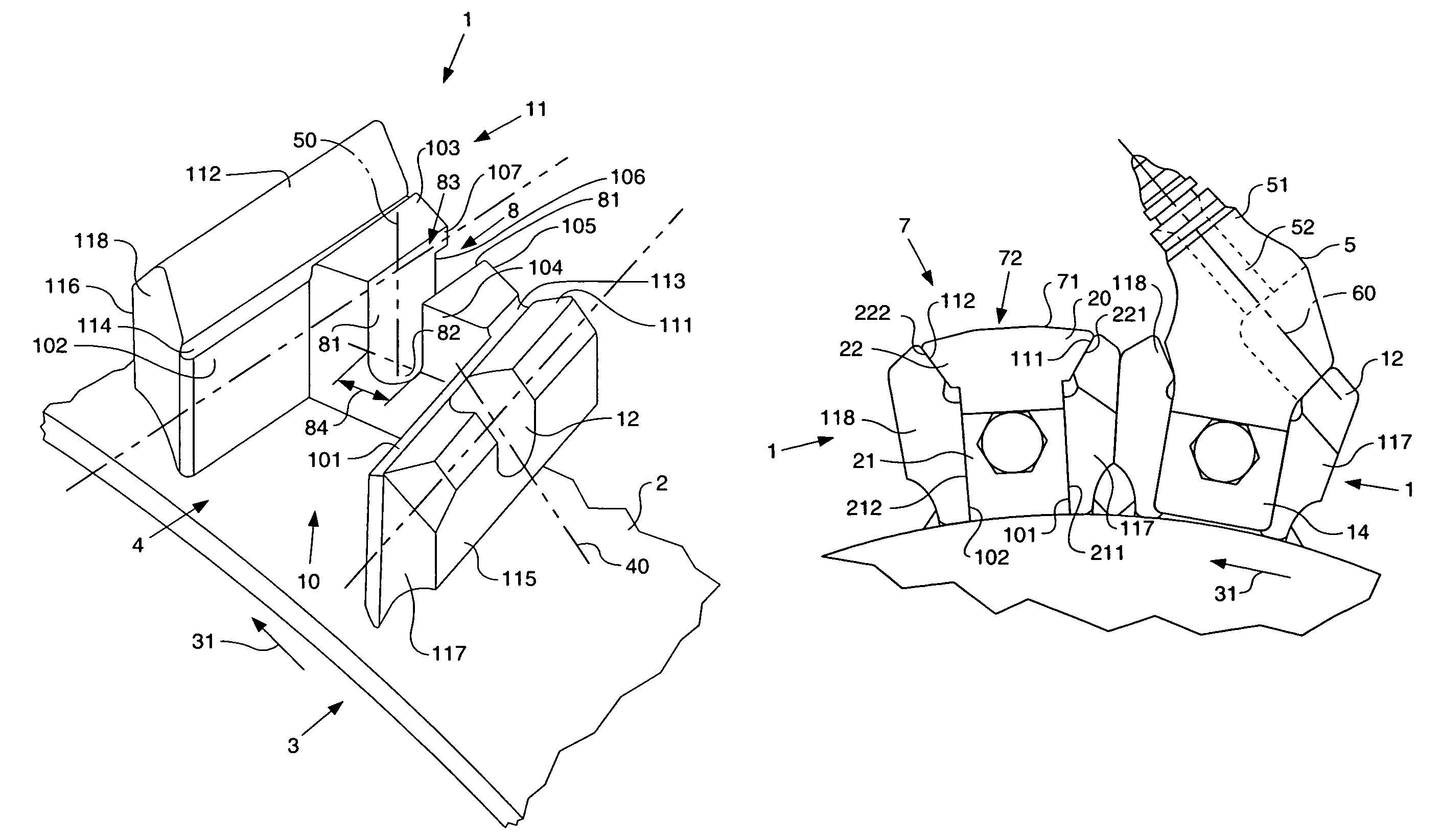
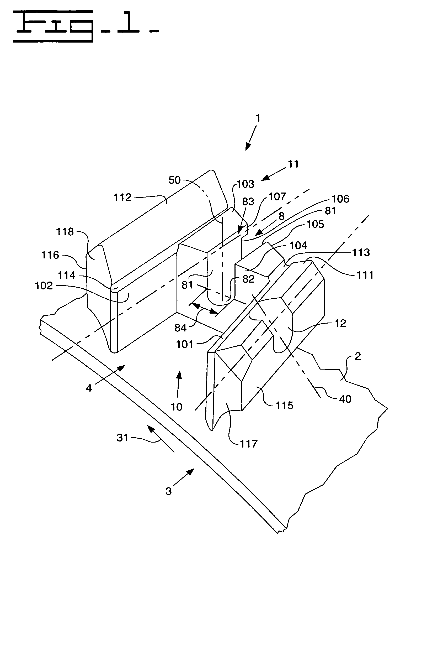
[0026]With reference to FIGS. 1 to 10, a support base 1 in accordance with a preferred embodiment of the invention is mounted to the surface 2 of a tubular body of a milling drum 3. The milling drum 3 is part of a road work machine, in particular of a scarifier (not shown) to remove road surfaces. In operation, the milling drum 3 is rotated in a working or milling direction as indicated by an arrow 31 in FIGS. 1 to 3.

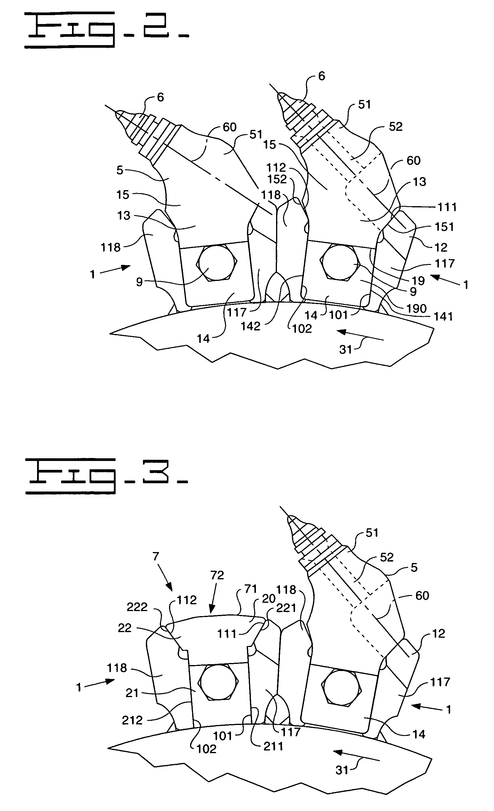
[0027]Preferably the support base 1 is an integral piece of metal and is fixedly mounted onto the surface 2 by welding. As can be seen in FIG. 1, the support base 1 has wall portions forming a recess 4 in which, as shown in FIG. 3, a body, i.e. either a toolholder 5 holding a tool 6 or a protection cover 7, can be accommodated and fixedly mounted to the support base 1. In case of the toolholder 5, it is seen in FIGS. 2 and 3 that it is mounted with a tip of the tool 6 pointing in the direction of rotation 31 of the milling drum. As can be seen in FIG. 3, the protection ...


PUM

PropertyMeasurementUnit
Angleaaaaaaaaaa

Abstract

A support base (1) which is to be mounted to the surface (2) of a milling drum (3) defining a direction of rotation (31) includes a recess (4) adapted to receive removably a shank portion (14; 21) of a body (5; 7) to be fixedly mounted to said support base (1). The recess (4) has a first side surface (101) facing into said direction of rotation (31) which is adapted to contact said shank portion (14; 21). The support base (1) further includes a reaction surface (111) adjacent to said first side surface (101) and also facing in said direction of rotation (31), wherein the reaction surface (111) is disposed at an angle of more than 180° with respect to said first side surface (101) and is adapted to bear against a support surface (151) of said body (5; 7).

Description

TECHNICAL FIELD[0001]The present invention generally relates to a support base for a toolholder of a milling drum, and in particular to a tool arrangement on milling drums of scarifiers.BACKGROUND ART[0002]Scarifiers are working machines used for working and removing soils, in particular for making roads. In their standard constructional form these machines are provided with a milling drum having a plurality of active elements, e.g. cutting or milling elements, that—during rotation of the milling drum—come into contact with the surface to be removed and crush it.[0003]In some prior art scarifiers, each active element is a tool arrangement consisting of a support base fixed to the tubular body of the milling drum, wherein the support base accomodates a respective toolholder in which a milling tool is removably inserted, for example, by pressing it into the toolholder.[0004]The active elements are arranged on the milling drum corresponding to one or more right hand and left hand spira...

Claims


Application Information

Patent Timeline
IPC IPC(8): E21C35/18B28D1/18E02F9/28E21C35/19
CPCB28D1/188E02F9/2866E21C35/19E21C2035/191E21C2035/1826E21C35/188E21C35/191
Inventor SANSONE, DARIORUBINI, ROBERTO
Owner CATERPILLAR PAVING PROD INC
Why Eureka
Try Eureka