Cover for coupling head

a technology for coupling heads and covers, which is applied in the direction of railway couplings, railway components, railway coupling accessories, etc., can solve the problems of failure of known protective devices, failure of coupling arrangement components or assemblies, and inability to protect the assemblies or components of the entire coupling arrangement from environmental influences

Inactive Publication Date: 2007-03-20
VOITH PATENT GMBH +1
View PDF5 Cites 6 Cited by
  • Summary
  • Abstract
  • Description
  • Claims
  • Application Information

AI Technical Summary

Benefits of technology

[0010]The advantages to the device according to the invention are in particular that the shroud, which can be pivoted from a working or decoupling state, in which it is arranged essentially perpendicularly in front of the coupling head, and into a resting or coupling state above the coupling, makes it possible to achieve a highly effective and especially easily realizable device for protecting the coupling head, in particular the moving assemblies and electrical contact arrangements situated therein, against environmental influences, such as dirt, snow, icing and moisture, and also against mechanical influences, such as unforeseen impacts. In this case, it is provided that this shroud can be pivoted into a resting or coupling state above the coupling, thereby further ensuring an automatic coupling process between two vehicles with integrated coupling head cover. Placing the shroud in front of the coupling head according to the invention ensures that the cover envelops the entire coupling head with all integrated assemblies or components in the protective area. This not only ensures that any air duct couplings and / or electrocontact couplings present in the coupling arrangement are nearly maintenance-free and always ready for use under any weathering conditions, but also that the moving assemblies located in the coupling arrangement are permanently protected in particular against coarse dirt and icing, also making them nearly maintenance-free and always ready for use. This makes it possible to use such coupling arrangements much more efficiently and cost-effectively than conventional coupling arrangements, which must be periodically maintained and cleaned. Protecting the coupling arrangement against icing in winter further eliminates the process of deicing the coupling arrangements, which involves significant technical or economic outlays and difficulties to accomplish.
[0020]It is particularly preferred to provide a seal between the front edge of the frame and the edge of the shroud. The seal provides reliable protection against weathering influences, in particular moisture, since the edge of the shroud with the provided seal abuts the edge of the frame lying opposite when the shroud is in the working or decoupling state.

Problems solved by technology

However, the protective device disclosed herein does not make it possible to also protect the assemblies or components of the coupling arrangement against environmental influences, such as dirt, ice or icing.
The disadvantage to known protective devices of the kind mentioned at the outset is that they do not afford sufficient protection to the components or assemblies of the entire coupling arrangement against mechanical loads or environmental influences.
In addition, efforts to indicate or arrange a cover or similar device in the coupling arrangement in such a way that it can be quickly replaced or subsequently installed without any special outlay through simple assembly on the coupling have thus far met with failure in known protective devices.

Method used


Image

  • Cover for coupling head
  • Cover for coupling head
  • Cover for coupling head

Examples


Embodiment Construction

)

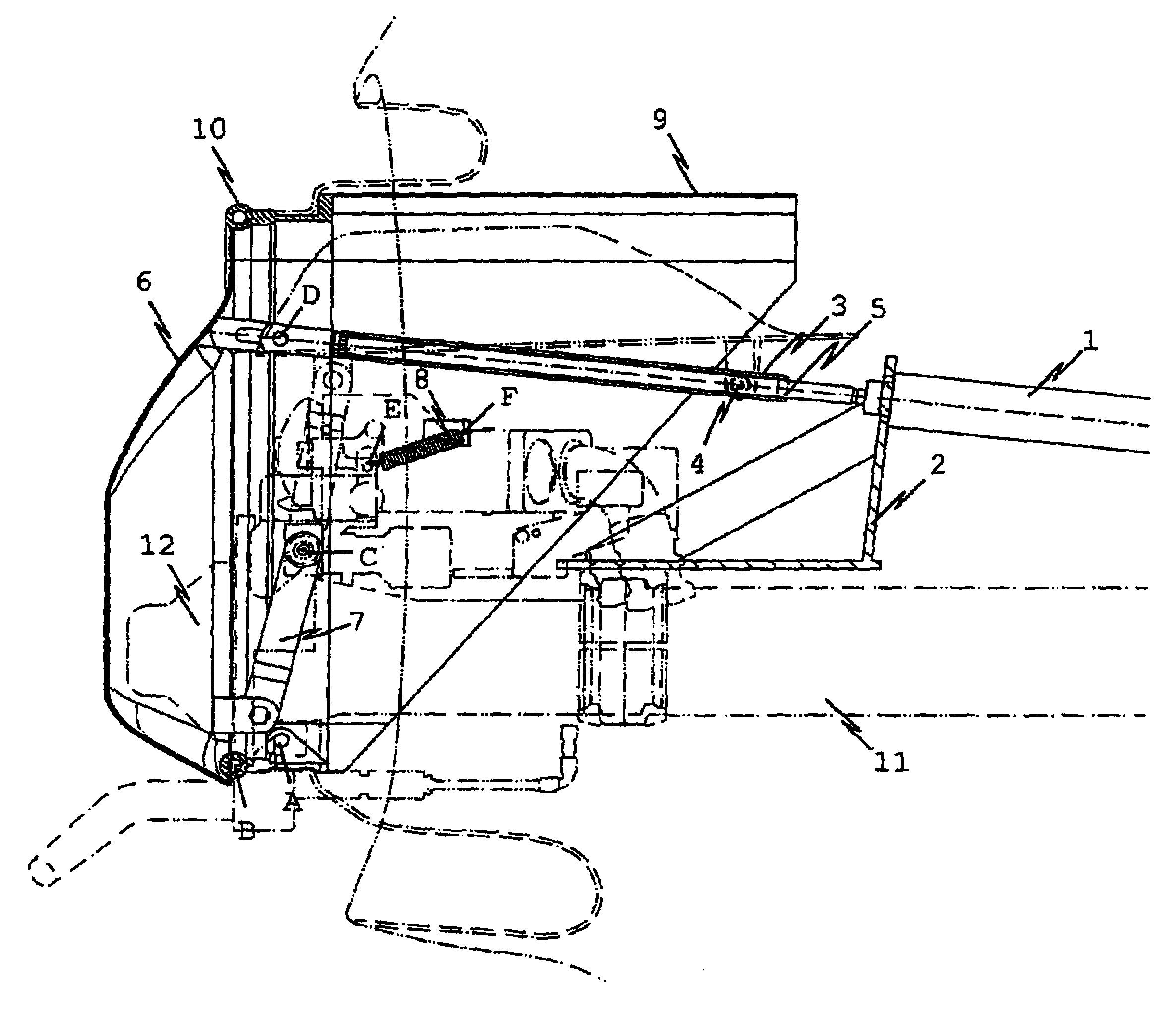
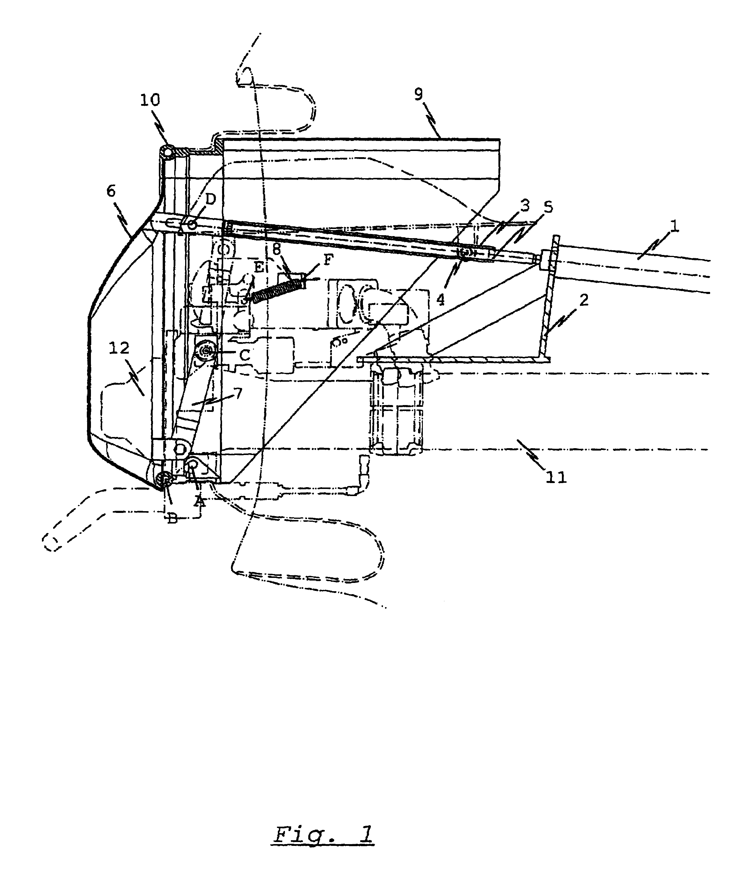
[0025]FIG. 1 shows a diagrammatic side view of the coupling cover according to the invention in a preferred embodiment. In this case, the cover is in the working state, in which the shroud 6 protects the coupling head 12, and particularly the moving assemblies situated therein, against environmental influences, such as dirt, snow, icing, etc. In this embodiment, the actuator is designed as a cylinder 1, which is rigidly mounted to the coupling 11 via the cylinder receptacle 2.

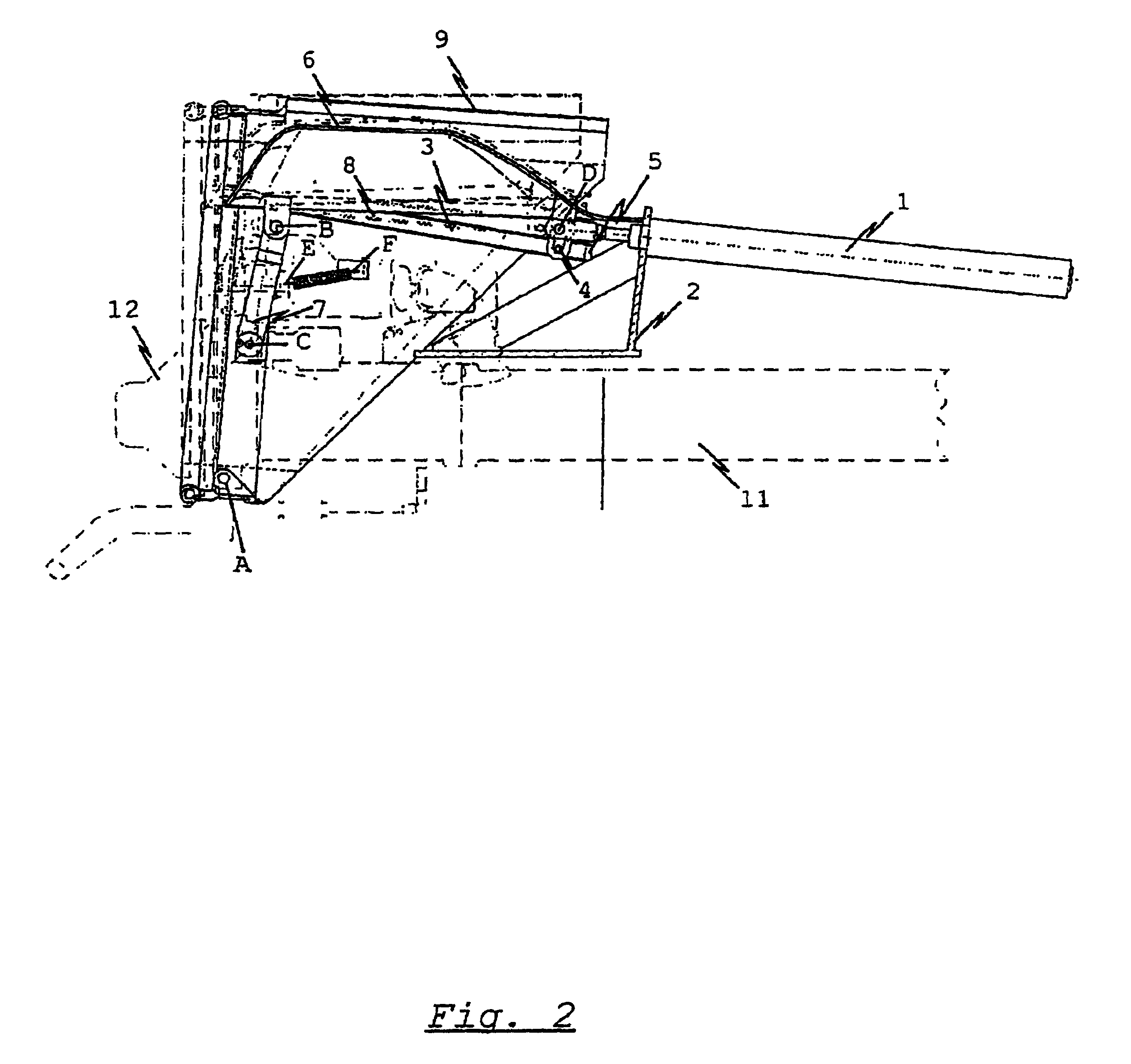
[0026]The piston rod of the cylinder is connected with the shroud 6 by means of a joint D. The shroud 6 can be pivoted around fulcrums B and C via a hinged arm 7, which resembles a lever, and is linearly guided through the rolls 4 in guiding rails 3. The shroud 6 is designed to pivot around fulcrums B and D with a hinge arrangement 7, B, C, D, wherein brackets 14, 15 are provided on the shroud, connected with D at the top and with B at the bottom.

[0027]The guiding rails 3, spring suspension point F and fulcrum...


PUM


Abstract

The invention relates to a cover for a coupling head to protect a coupling head (12), particularly the moving components found therein, against environmental influences such as dirt, snow, icing and mechanical shocks. The functioning of the coupling head cover is such that an automatic coupling process between two vehicles is further guaranteed. A shroud (6) is provided, which may be pivoted from a working or uncoupled position, in which the shroud (6) is arranged in an essentially vertical position in front of the coupling head (6), into a rest or coupled position above the coupling (11). A jointed arrangement (7,B,C,D) is provided for pivoting the shroud (6), connected to both the shroud (6) and the coupling (11) or a frame (9) arranged on the coupling (11).

Description

BACKGROUND OF THE INVENTION[0001]1. Field of the Invention[0002]The invention relates to a cover for a coupling head, in particular for a coupling head of an automatic central coupling or central buffer coupling for a freight car given a multiple-unit rail vehicle, as well as to a method for pivoting the coupling head cover.[0003]2. Background Art[0004]A device for protecting assemblies or components in coupling arrangements is basically known from rail vehicle technology. For example, German Patent Specification DE 43 12 405 A1 describes a central buffer coupling for rail vehicles with a protective device, wherein the protective device also ensures protection in the area of the draw and buffering gear without any additional retrofitting, even in couplable or coupled rail vehicles. In this case, the coupling head of the respective central buffer coupling is equipped on both sides with protective straps, which are hinged to the frame of the rail vehicle. Hinging the protective straps...

Claims


Application Information

Patent Timeline
IPC IPC(8): B61G1/00B61G7/00
CPCB61G7/00
Inventor HEINISCH, ANDREASRADEWAGEN, CHRISTIAN
Owner VOITH PATENT GMBH
Why Eureka
Try Eureka