
Off road vehicle

a technology for vehicles and vehicles, applied in the direction of electric vehicles, steering gears, power-driven steering, etc., can solve the problems of fuel waste, two steering systems clashing, and scuffing of the ground traversed,

Inactive Publication Date: 2007-03-20
SPARK IAN JAMES
View PDF6 Cites 26 Cited by
  • Summary
  • Abstract
  • Description
  • Claims
  • Application Information

AI Technical Summary

Benefits of technology

"The invention aims to increase the tractability, stability, maneuverability, and safety of wheeled vehicles while minimizing fuel consumption and damage to the ground. The technical effects of the invention include reducing the range of wheel speed ratios that cause scuffing, eliminating the need for one steering system to compromise the other, and improving the stability and traction of the vehicle in difficult conditions. The invention also addresses the problem of instability and traction when trying to achieve a different center of curvature for the path of the vehicle."

Problems solved by technology

In general these two steering systems will conflict with one another when each tries to achieve a different centre of curvature for the path of the vehicle.
This conflict causes a braking effect, which results in fuel wastage, scuffing of the ground traversed and associated tyre wear.
Unfortunately, making one steering system compliant with the other leads to stability and traction problems when the vehicle is operated in difficult conditions.
If the sideways, forwards or backwards force on the vehicle increases and / or the coefficient of friction between the tyres and the ground decreases, the system used to manoeuvre the vehicle will eventually fail.
In this environment weight is transferred from the uphill drive wheel making it liable to spinning.
Although the stability of the traditional tractor can be improved by the use of a limited slip differential or a lockable differential, it is somewhat illogical to provide a differential in the first instance along with a subsidiary system which either impedes its operation, or stops it altogether.
Because these castors cannot exert any sideways force on their end of the vehicle, the tendency for this end to swing down the hill can only be prevented by the two drive wheels applying opposing forces to the vehicle—even though they may be driven at the same speed.
As the steepness of the slope traversed increases the uphill drive wheel eventually loses traction and the front of the vehicle swings down the hill.
This method of manoeuvring causes extreme scuffing with associated ground damage, fuel wastage and tyre or track wear.
As a consequence, rotation and translation in a confined space can be a problem.

Method used


Image

  • Off road vehicle
  • Off road vehicle
  • Off road vehicle

Examples


Embodiment Construction

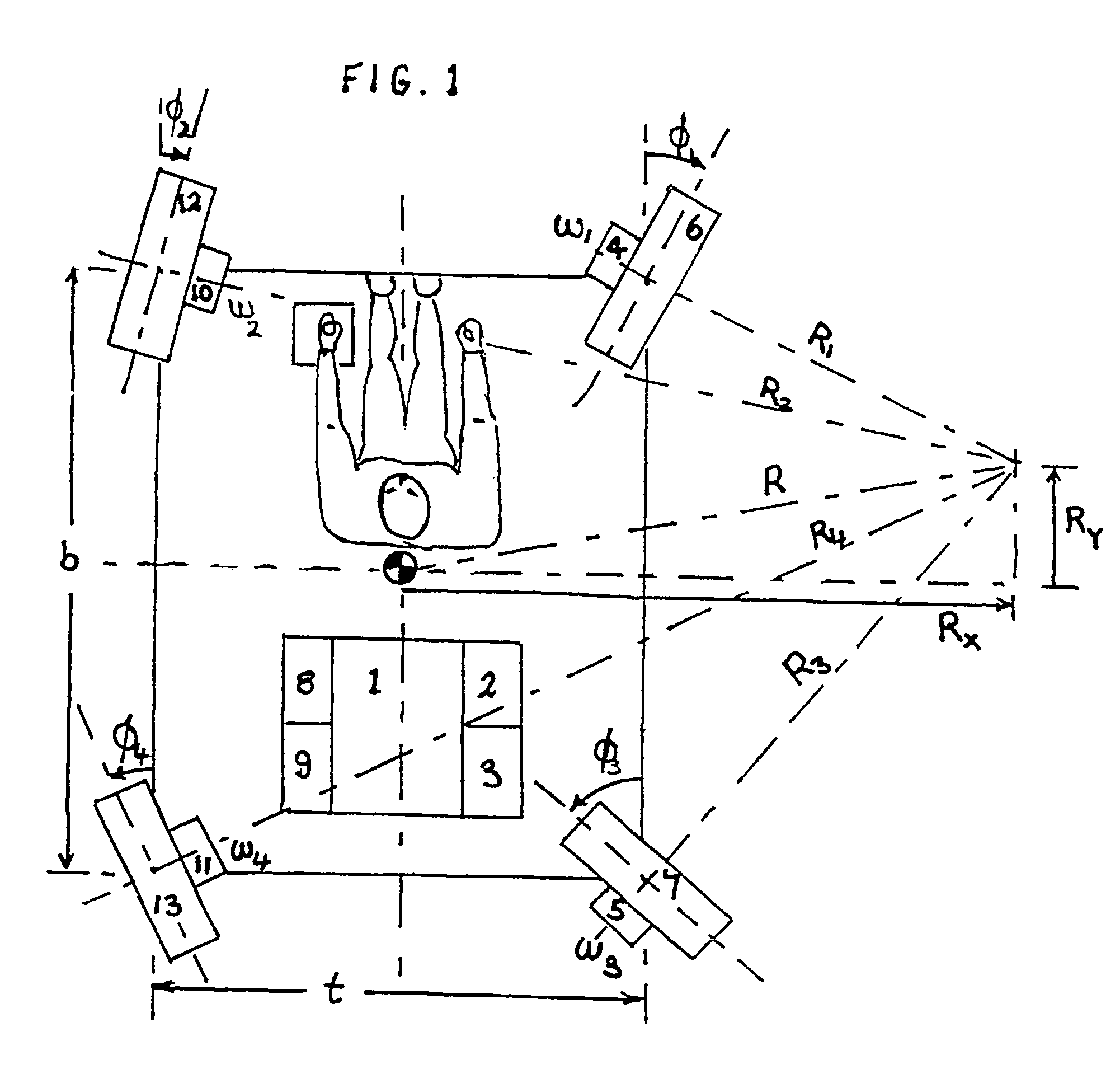
[0025]In the four wheel steering / four wheel drive variant of the invention depicted in FIG. 1, an internal combustion engine 1 drive two right hand variable displacement hydraulic pumps 2 and 3 which in turn drive hydraulic motors 4 and 5 mounted in the steerable front and rear right hand wheels respectively. The internal combustion engine 1 also drives left hand variable displacement pumps 8 and 9 which in turn drive hydraulic motors 10 and 11 which are mounted in the steerable front and rear left hand wheels 12 and 13 respectively

[0026]The angles of the wheels 6, 12, 7 and 13 are shown as φ1, φ2, φ3 and φ4 respectively. The rotational speed of the wheels 6, 12, 7 and 13 are ω1, ω2, ω3 and ω4 respectively.

[0027]The driver controls the vehicle by selecting the radius of curvature of the vehicle's path and the sense of rotation by rotating the joystick. If the joystick is not turned the radius of curvature of the path of the vehicle will be infinity and the vehicle will move in a str...


PUM


Abstract

There are two basic methods of steering a wheeled vehicle. One method is to turn one or more steerable wheels. The other is to drive one or more left hand wheels independently of one or more right hand wheels. Traditional vehicles address the potential conflict between the two steering systems by either disabling one system or by causing one to overpower the other. This leads to skidding or scuffing problems respectively. In the present invention both steering systems are enabled but are integrated by means of an on board computer so that they always act in unison. This mutual reinforcement will allow the invention to operate safely on steep or slippery slopes while minimizing fuel consumption and ground damage. The invention will also be more maneuverable than traditional vehicles since it is capable of both pure rotation and pure translation or any combination of rotation and translation.

Description

TECHNICAL FIELD[0001]The invention relates to a means of increasing the tractability, stability, manoeuvrability and safety of wheeled vehicles while at the same time minimizing fuel consumption and damage to the ground traversed.DESCRIPTION OF PRIOR ART[0002]The following patents or patent applications allude to the problem to be solved by the present invention, but do not go far enough to describe a complete solution.[0003]WO 98 / 19875 A1 (GRANT) 14 May 1998 merely states that the drive wheel speeds and angles are calculated by a computer.[0004]WO 00 / 32462 A1 (Grant) 8 Jun. 2000 describes equations for drive wheel speeds and wheel angles. These equations are hard to decipher since the variables are poorly defined. The equations for wheel speeds are clearly different from those described in the present invention, and as such must be incorrect. Grant's equations for wheel speed may approximate to the correct equations when the radius of curvature of the path of the vehicle is large.[...

Claims


Application Information

Patent Timeline
Patent Type & Authority Patents(United States)
IPC IPC(8): B62D7/15B62D9/00B60L15/20B62D11/04
CPCB60L15/2036B62D7/1509B62D11/04B62D9/00Y02T10/7275Y02T10/64Y02T10/72
Inventor SPARK, IAN JAMES
Owner SPARK IAN JAMES
Learn More