Eureka AIR delivers breakthrough ideas for toughest innovation challenges, trusted by R&D personnel around the world.

Testing apparatus and method of deriving Young's modulus from tensile stress/strain relationships

a technology of tensile stress and relationship, applied in the direction of measurement devices, instruments, scientific instruments, etc., can solve the problems of brittleness of well cement compositions when cured, affecting isolation, and difficulty in obtaining wellbore isolation and maintaining mechanical integrity, etc., to achieve accurate measurement of tensile strength of various cement systems, improve fit for purpose designs, and improve the effect of mechanical properties

Inactive Publication Date: 2007-03-20
BAKER HUGHES HLDG LLC
View PDF10 Cites 21 Cited by
  • Summary
  • Abstract
  • Description
  • Claims
  • Application Information

AI Technical Summary

Benefits of technology

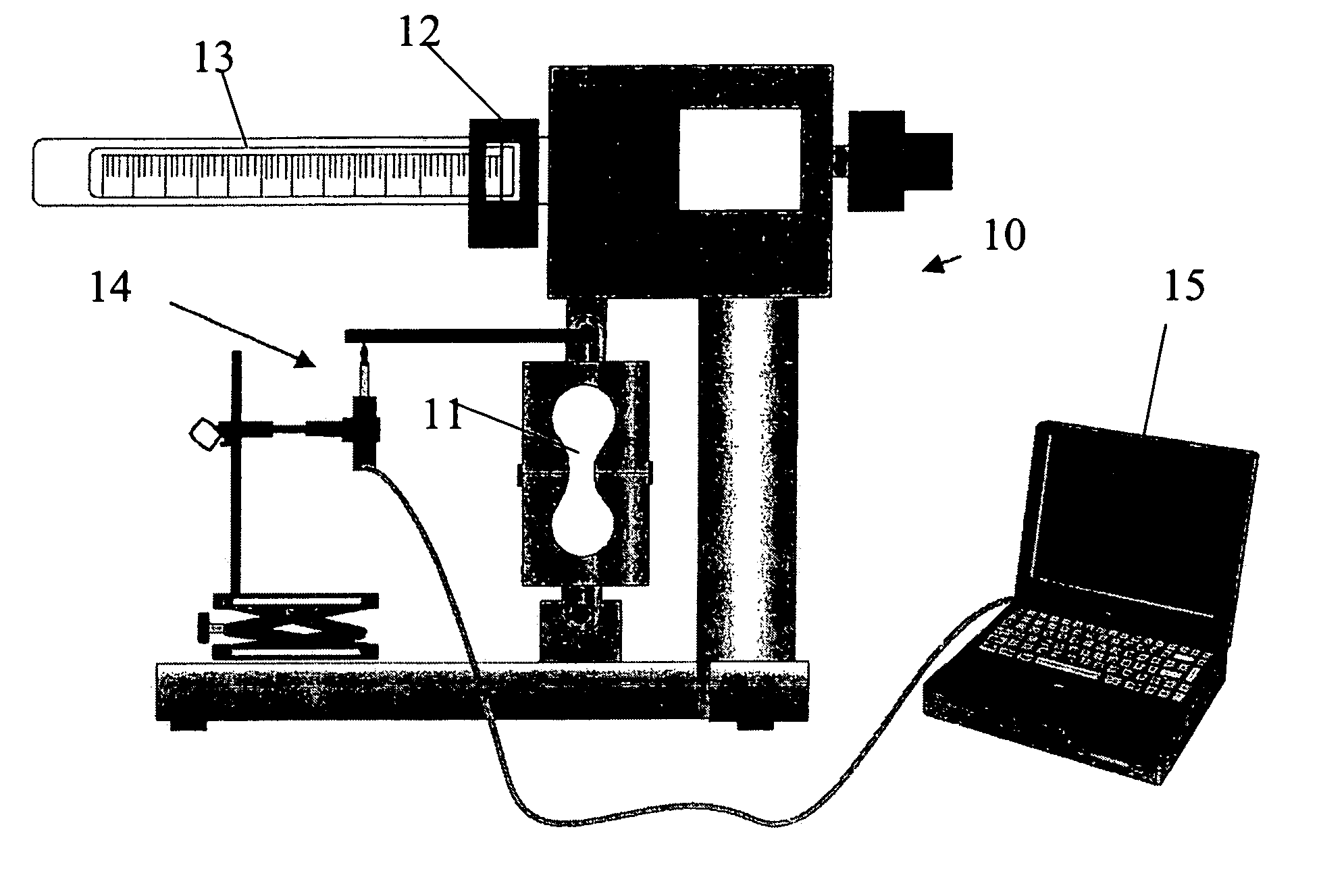
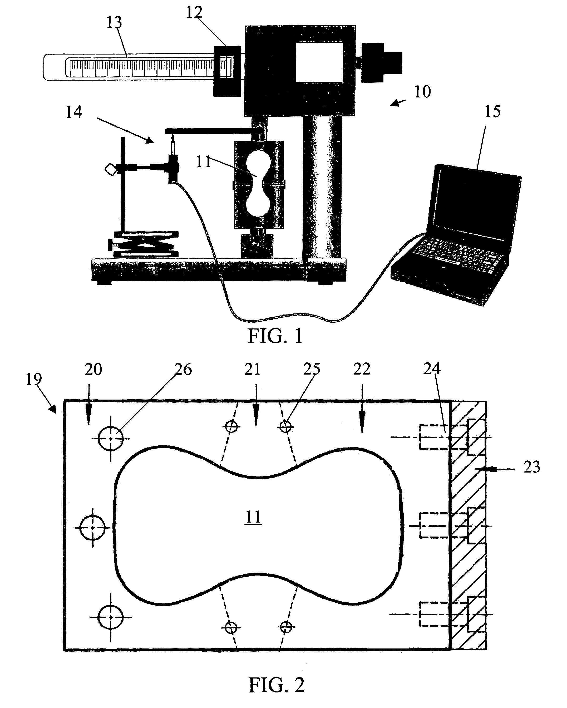
[0031]The following provides a means to combine static flexural / tensile strength testing and elasticity measurements of cements. Since most cements fail in the annulus of a well while under tension, or a combination of tension and compression, the ratio of axial stress to axial strain is an important factor when the axial stress was in tension, or a combination of tension and compression instead of just testing in compression. Using a testing device based on these methods, the present invention can generate Young's Modulus values for different cement compositions under stresses that are similar to the conditions occurring in an actual wellbore. The present invention allows the user to calculate the induced stresses that would occur if the different systems were used in a well, and thus develop better fit for purpose designs.
[0033]Since current ASTM testing is carried out under atmospheric conditions, this invention provides for an alternative means to accurately measure tensile strength of various cement systems under more realistic field conditions. The invention discloses an apparatus that allows for the elimination of data influenced by factors such as cooldown and depressurization of cured cement samples.

Problems solved by technology

Cement operations performed in wellbores under these high stress conditions present problems including difficulty in obtaining wellbore isolation and maintaining the mechanical integrity of the wellbore.
Once established, this isolation may be impacted by the particular stresses associated with the environment found in the wellbore during operations.
Furthermore, well cement compositions may be brittle when cured.
These cement compositions may fail due to tensional and compressional stresses that are exerted on the set cement.
Relatively high temperatures may induce stress conditions and / or relatively high fluid pressures encountered inside cemented wellbore pipe strings during operations such as perforating, stimulation, injection, testing, or production.
In addition, variations in temperature and internal pressure of the wellbore pipe string may result in radial and longitudinal pipe expansion and / or contraction which tends to place stress on the annular cement sheath existing between the outside surface of a pipe string and the inside formation surface or wall of a wellbore.
In other cases, cements placed in wellbores are subjected to mechanical stress induced by vibrations and impacts resulting from operations.
The following testing method fail to provide a method of testing under these conditions.
This testing method therefore fails to simulate the stresses encountered in the higher temperature and pressure conditions of the wellbore environment.
This testing method therefore also fails to simulate the stresses encountered in the higher temperature and pressure conditions of the wellbore environment.
Tensile failure occurs rather than compressive failure because the areas of load application are in a state of triaxial compression.
This testing method therefore fails to simulate the stresses encountered in the higher temperature and pressure conditions of the wellbore environment.
None of these testing methods provides for the creation of samples under the temperature and pressure conditions found in a wellbore environment.

Method used


Image

  • Testing apparatus and method of deriving Young's modulus from tensile stress/strain relationships
  • Testing apparatus and method of deriving Young's modulus from tensile stress/strain relationships
  • Testing apparatus and method of deriving Young's modulus from tensile stress/strain relationships

Examples


examples

[0072]Three cement specimens were cured at atmospheric pressure, 198° F., and 20.0 ppg. The slurry design was used for this experiment was primarily Norcem AS G with 45% W-10+20% MPA-3+0.01797 gps CD-31L+0.0839 pgs R-15L+0.02 gps FP-6L. A maximum cycle load of 5000 N (2027 psi) was applied.

[0073]The deflection versus time graph in FIG. 9 shows the consistency of the deflection of the samples prior to failure. The peaks of the graphs are very similar and the time to failure of the three samples has a similar width on the X-axis.

[0074]FIG. 10 shows the flexural stress (psi) versus the deflection (inches) for one of these samples. The linear increase of deflection as the stress increased shows the consistency of the results. When the deflection is compared to the Young's Modulus, as shown in FIG. 11, the graph shows the flattening the Young's modulus as the sample's deflection nears the failure point.

[0075]Two additional samples are shown in FIG. 11 in a tensile strength test. Using th...


PUM

PropertyMeasurementUnit
temperatureaaaaaaaaaa
Young's modulus of elasticityaaaaaaaaaa

Abstract

A method of testing and a tester apparatus to determine the axial stress and strain of cements under the temperature and pressures encountered by cement during use in wellbore environments. Using these stress and strain measurements, the Young's Modulus may be established for a material at the encountered temperature and pressure of the wellbore. By combining static tensile strength testing and elasticity measurements of cements, Young's Modulus values for different cement compositions under stresses that are similar to the conditions occurring in an actual wellbore are possible.

Description

FIELD OF THE INVENTION[0001]The invention relates to testing methods and devices used for testing of the mechanical properties of cement including cement formed in wellbore environments.BACKGROUND OF THE INVENTION[0002]Cement is used in the casing and liners of a wellbore. The annular space between the casing / lining and the wellbore is filled with a predetermined quantity of a cement mixture, which after hardening retains the casing / liner in place in the wellbore. The cement mixture is pumped in at the top end of the casing or liner, down to the lower end thereof and out into and up the annular space on the outside of the casing / liner.[0003]Cementing is employed during many phases of wellbore operations. For example, cement may be employed to cement or secure various casing strings and / or liners in a well. Cementing may also be used to repair casing and / or to achieve formation isolation. Additionally, cementing may be employed during well abandonment. Cement operations performed in ...

Claims


Application Information

Patent Timeline
Patent Type & Authority Patents(United States)
IPC IPC(8): G01N3/00G01N3/02G01N3/04G01N3/08G01N33/38
CPCG01N3/08G01N33/383G01N2203/0017G01N2203/0075G01N2203/0222G01N2203/047G01N2203/0246G01N2203/0252G01N2203/0268G01N2203/0298G01N2203/023
Inventor GO BONCAN, VIRGILIOROGERS, MURRAY J.HEINOLD, THOMASDILLENBECK, ROBERT L.
Owner BAKER HUGHES HLDG LLC
Why Eureka
Eureka Blog
Learn More