
Multi-stable micro electromechanical switches and methods of fabricating same

a micro electromechanical switch and multi-stable technology, applied in the field of micro electromechanical switches, can solve the problems of wide application in many products and environments, conventional micro electromechanical switches consume too much power for practical use in demanding environments, and difficulties in isolating the switch actuation signal from the transmitted signal in such environments

Inactive Publication Date: 2007-03-13
MEDTRONIC INC
View PDF61 Cites 29 Cited by
  • Summary
  • Abstract
  • Description
  • Claims
  • Application Information

AI Technical Summary

Benefits of technology

The patent describes a micro electromechanical switch that can be used in various applications, including in the medical device field. The switch includes a moveable member and receiving terminals that can be actuated using electrostatic energy. The switch can be in a closed state or an open state, and can be used to switch between different electrical connections. The technical effect of this invention is to provide a reliable and efficient means for switching between different electrical connections, which can be useful in various medical applications.

Problems solved by technology

Although it would generally be desirable to include such tiny electromagnetic switches in medical devices (e.g. pacemakers, defibrillators, etc.) and other applications, several disadvantages have prevented widespread use in many products and environments.
Most notably, many conventional micro electromechanical switches consume too much power for practical use in demanding environments, such as in a device that is implanted within a human body.
Moreover, difficulties often arise in isolating the switch actuation signal from the transmitted signal in such environments.
Further, the amount of energy (e.g. electrical voltage) typically required to actuate a conventional electromechanical switch may be too great for many practical applications, particularly in the medical field.

Method used


Image

  • Multi-stable micro electromechanical switches and methods of fabricating same
  • Multi-stable micro electromechanical switches and methods of fabricating same
  • Multi-stable micro electromechanical switches and methods of fabricating same

Examples


Embodiment Construction

[0016]The following detailed description is merely exemplary in nature and is not intended to limit the invention or the application and uses of the invention. Furthermore, there is no intention to be bound by any expressed or implied theory presented in the preceding technical field, background, brief summary or the following detailed description.

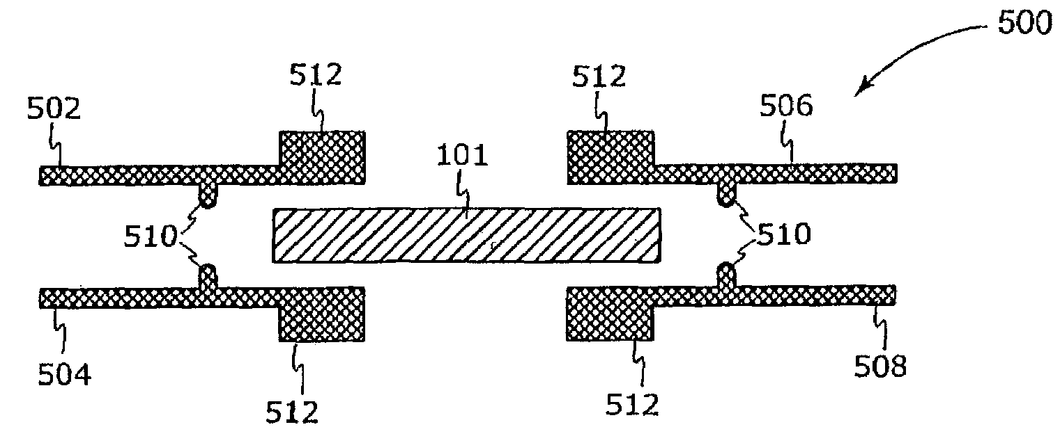
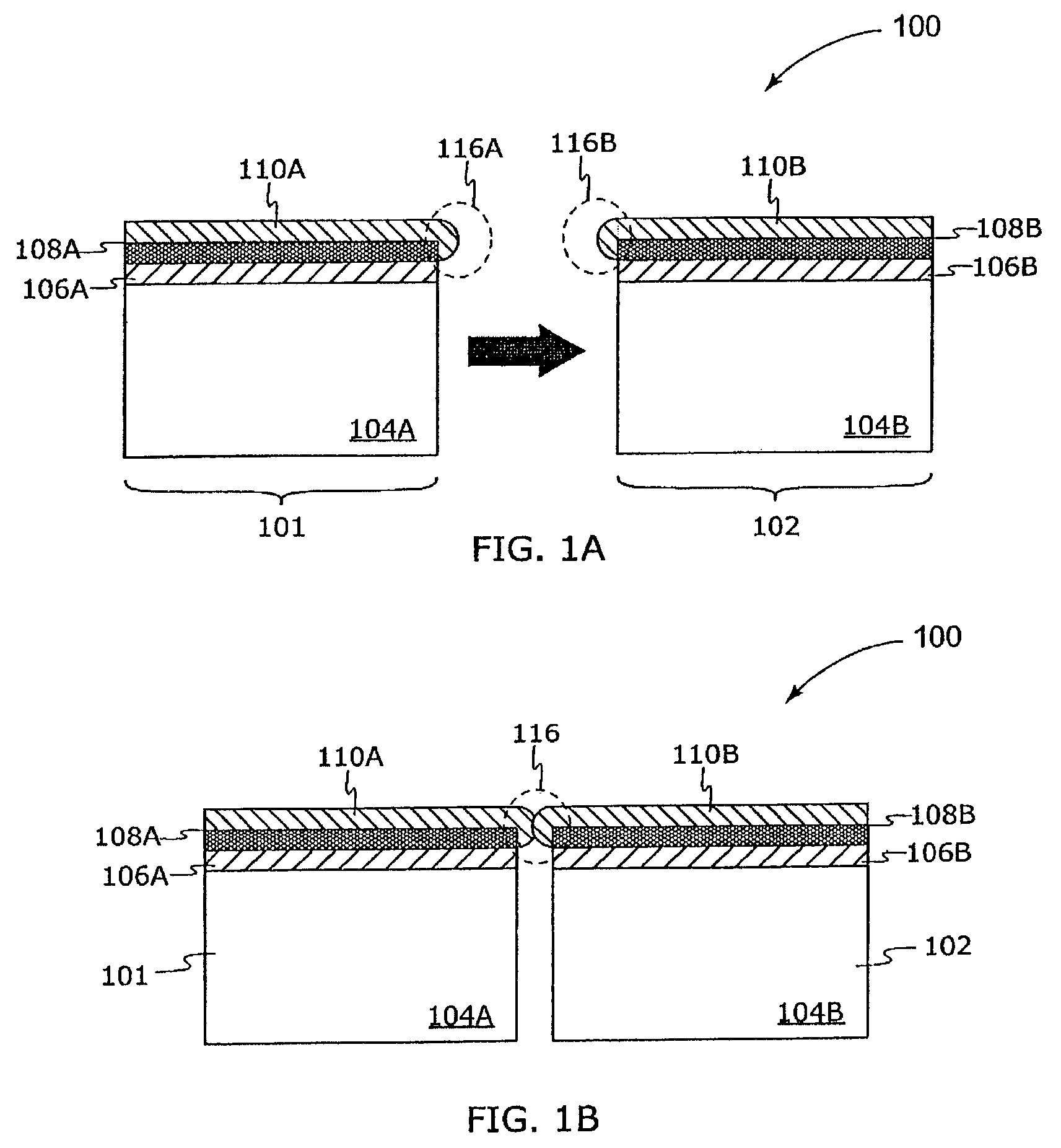
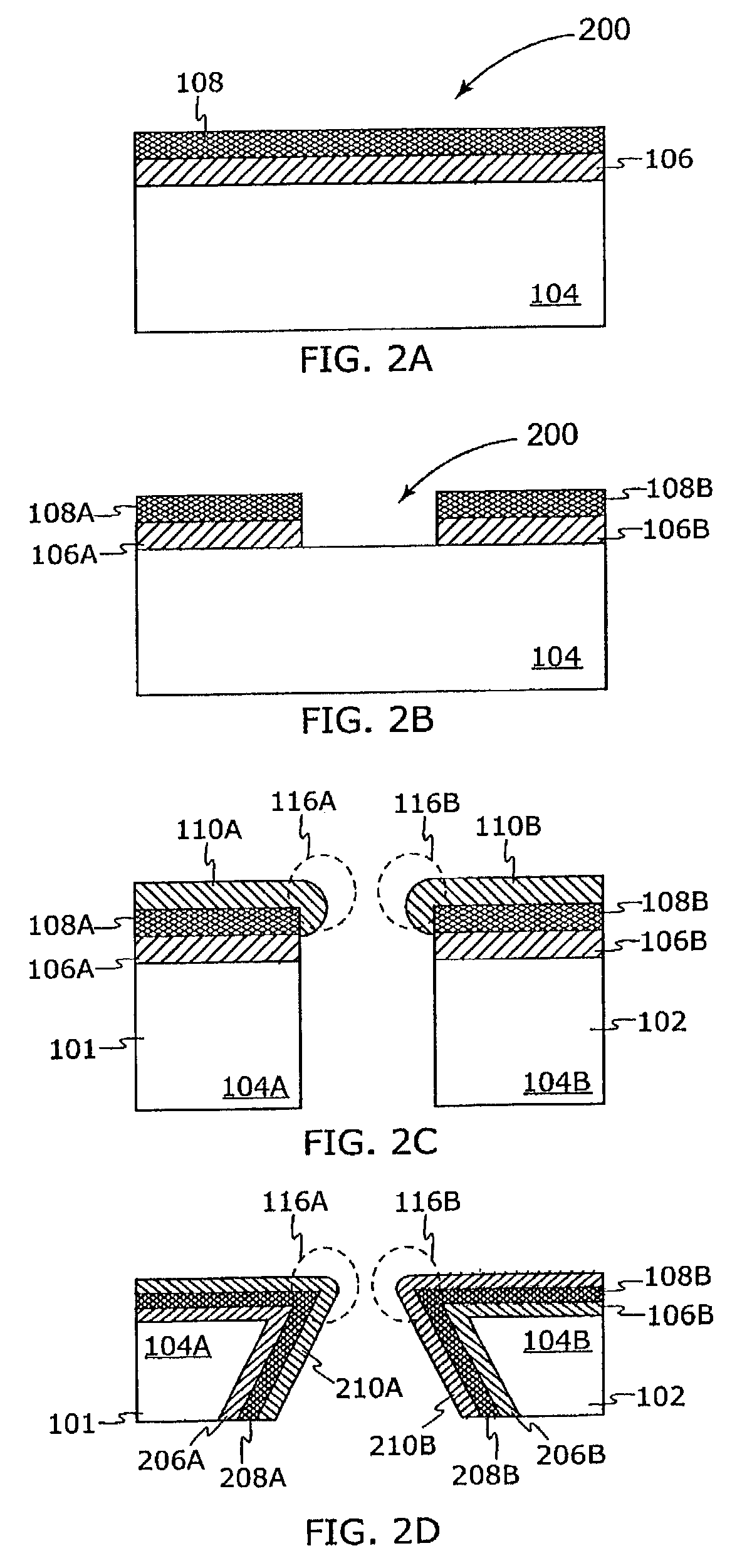
[0017]According to various exemplary embodiments, switches suitable for use in medical devices and the like are fabricated using conventional MEMS techniques. The switches suitably include a moveable armature, cantilever or other member that is capable of selectively engaging one or more receiving terminals to place the switch into a desired state. In various embodiments, the moveable member and / or receiving terminal(s) are fashioned with a protruding region formed of a noble metal (e.g. gold) or another conductive material to improve electrical connections within the switch. In further embodiments, the switch is configured to exhibit two ...


PUM

PropertyMeasurementUnit
sizeaaaaaaaaaa
actuation forceaaaaaaaaaa
activation forceaaaaaaaaaa

Abstract

A micro electromechanical (MEMS) switch suitable for use in medical devices is provided, along with methods of producing and using MEMS switches. In one aspect, a micro electromechanical switch including a moveable member configured to electrically cooperate with a receiving terminal is formed on a substrate. The moveable member and the receiving terminal each include an insulating layer proximate to the substrate and a conducting layer proximate to the insulating layer opposite the substrate. In various embodiments, the conducting layers of the moveable member and / or receiving terminal include a protruding region that extends outward from the substrate to switchably couple the conducting layers of the moveable member and the receiving terminal to thereby form a switch. The switch may be actuated using, for example, electrostatic energy.

Description

CROSS-REFERENCE TO RELATED APPLICATION[0001]Cross-reference is hereby made to commonly assigned related U.S. application Ser. No. 10 / 425,527, filed concurrently herewith, entitled “Micro Electromechanical Switches and Medical Devices Incorporating Same”, incorporated herein by reference in its entirety.TECHNICAL FIELD[0002]The present invention generally relates to electromechanical switches, and more particularly relates to micro electromechanical switches that have multiple stable states.BACKGROUND[0003]Switches are commonly found in most modern electrical and electronic devices to selectively place electrical, optical and / or other signals onto desired signal paths. Switches may be used to enable or disable certain components or circuits operating within a system, for example, or may be used to route communications signals from a sender to a receiver. Electromechanical switches in particular are often found in medical, industrial, aerospace, consumer electronics and other settings...

Claims


Application Information

Patent Timeline
Patent Type & Authority Patents(United States)
IPC IPC(8): H01H51/22B81B3/00B81B5/00H01H59/00
CPCB81B3/0054H01H59/0009B81B2201/018B81B2203/051Y10T29/49105H01H2001/0042H01H2001/0078
Inventor RECEVEUR, ROGIERHABETS, PHILIPPEDANZL, RALPH B.HOUBEN, RICHARD P. M.MATTES, MICHAEL F.
Owner MEDTRONIC INC
Learn More