
Method for calibrating timing clock

Inactive Publication Date: 2007-03-13
ADVANTEST CORP
View PDF4 Cites 4 Cited by
  • Summary
  • Abstract
  • Description
  • Claims
  • Application Information

AI Technical Summary

Benefits of technology

[0018]According to the present invention, a timing clock calibration method is capable of linearizing a timing clock in a short time with a high degree of accuracy.

Problems solved by technology

However, a conventional test apparatus has a problem that it cannot linearize the phase of the timing clock with a high degree of accuracy in a case where the shift clock contains a small phase linear error because linearization of the phase of the timing clock is performed by using the shift clock as a reference based on assumption that the shift clock generated by the shift clock generating section has highly accurate phase linearity.

Method used


Image

  • Method for calibrating timing clock
  • Method for calibrating timing clock
  • Method for calibrating timing clock

Examples


Embodiment Construction

[0027]The invention will now be described based on the preferred embodiments, which do not intend to limit the scope of the present invention, but exemplify the invention. All of the features and the combinations thereof described in the embodiment are not necessarily essential to the invention.

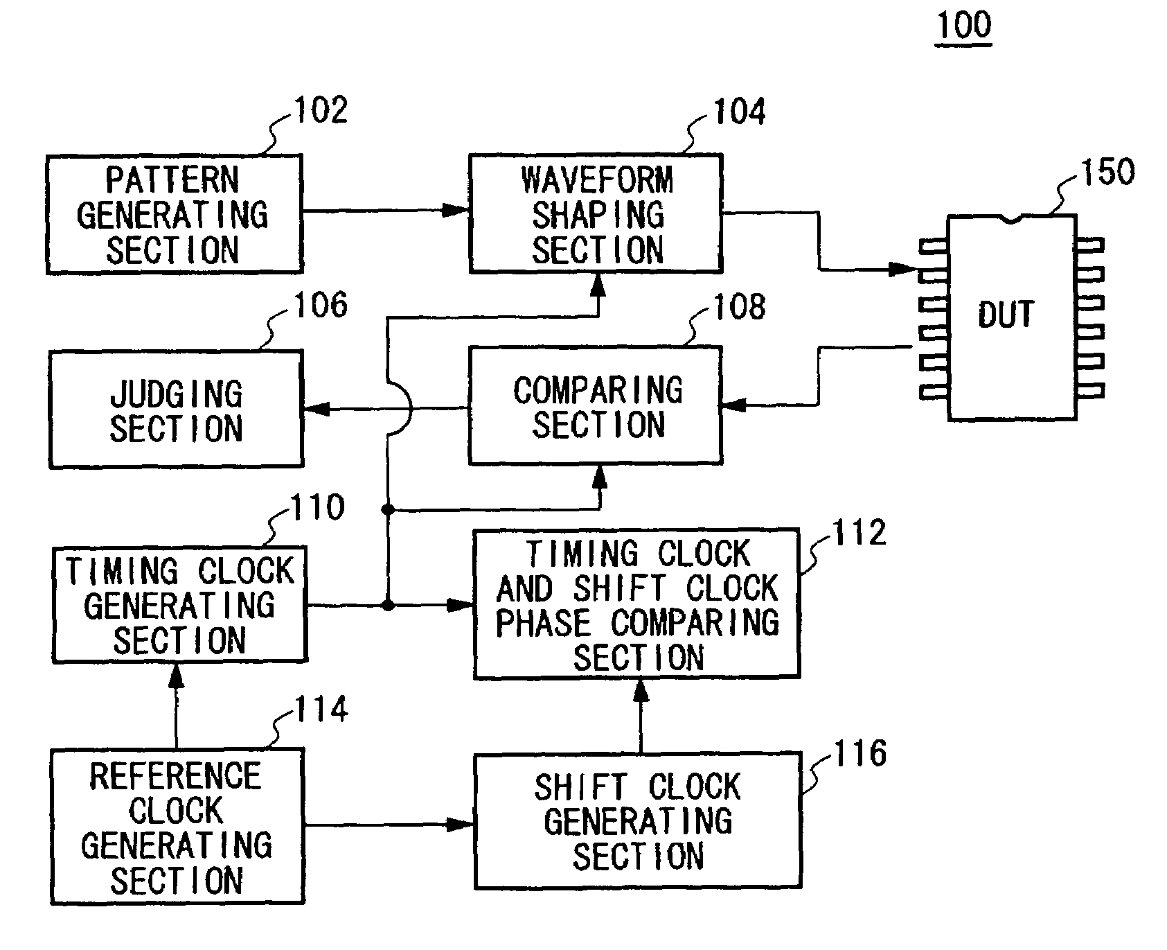
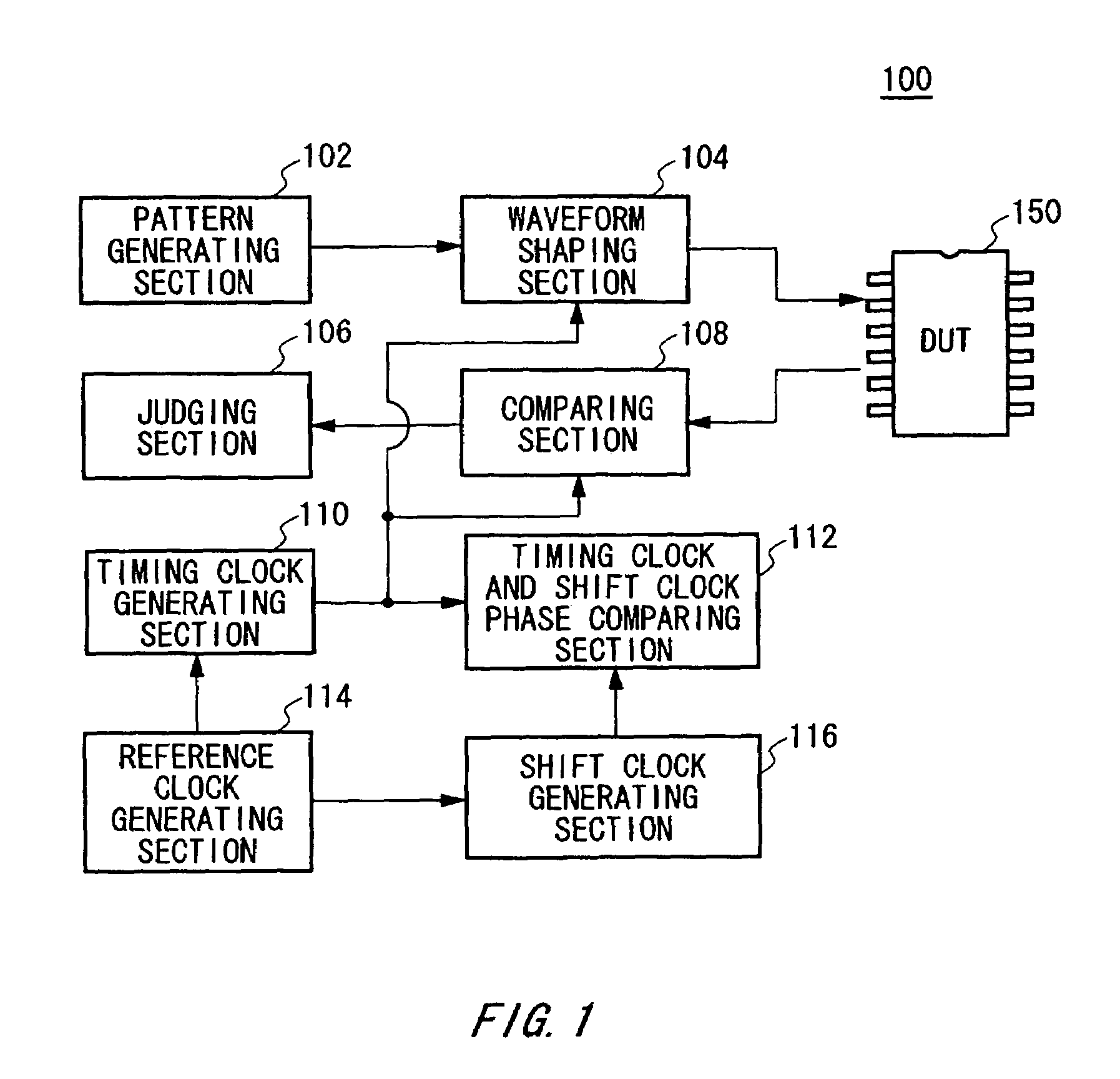
[0028]FIG. 1 shows an exemplary structure of a test apparatus 100 according to an embodiment of the present invention. The test apparatus 100 includes a pattern generating section 102, a waveform shaping section 104, a judging section 106, a comparing section 108, a timing clock generating section 110, a timing clock and shift clock phase comparing section 112, a reference clock generating section 114, and a shift clock generating section 116.

[0029]The reference clock generating section 114 generates a reference clock that is used as a reference in a test of a device under test 150 by the test apparatus 100. The timing clock generating section 110 delays the reference clock to generate a timi...


PUM


Abstract

A method for calibrating a timing clock is provided. The method includes the steps of calibrating a shift amount of an edge of a shift clock by using a period of the timing clock as a reference by detecting an edge of the timing clock more than once while changing the shift amount of the edge of the shift clock; shifting and generating the edge of the shift clock by a predetermined shift amount by the calibrated shift clock generating section; and calibrating a required delay amount for delaying the timing clock by time corresponding to the predetermined shift amount by detecting the edge of the shift clock shifted by the predetermined amount while changing a delay amount of the timing clock.

Description

CROSS REFERENCE TO RELATED APPLICATION[0001]The present application claims priority from a Japanese Patent Application No. 2004-004733 filed on Jan. 9, 2004, the contents of which are incorporated herein by reference.BACKGROUND OF THE INVENTION[0002]1. Field of the Invention[0003]The present invention relates to a method for calibrating a timing clock. More particularly, the present invention relates to a timing clock calibration method for calibrating a timing clock generating section that generates a timing clock indicative of a timing at which a test signal is to be fed to a device under test.[0004]2. Related Art[0005]A test apparatus for testing a semiconductor device includes a timing clock generating section that generates a timing clock for causing generation of a given waveform, that is a fundamental function of the test apparatus, a shift clock generating section that generates a shift clock for linearizing the timing clock, and a timing clock and shift clock phase comparin...

Claims


Application Information

Patent Timeline
IPC IPC(8): G01R35/00G01R23/175G01R31/319G01R31/3193
CPCG01R31/3191G01R31/31937G01R31/31922H03K5/15G01R31/28G01R31/3183
Inventor DOI, MASARU
Owner ADVANTEST CORP
Learn More