
Methods and apparatuses of separating cells using magnets and droplet type cell suspension

a technology of cell suspension and magnets, applied in the field of methods and apparatuses of separating cells, can solve the problems of difficult to discriminate cells at a time, cells to pass through,

Inactive Publication Date: 2007-03-13
KOREA INST OF SCI & TECH
View PDF1 Cites 67 Cited by
  • Summary
  • Abstract
  • Description
  • Claims
  • Application Information

AI Technical Summary

Benefits of technology

The present invention provides methods and apparatuses for separating cells using magnets and droplet type cell suspension. The technical effects of the invention include the ability to effectively separate cells without adjusting the apparatus based on the size of cells being separated, the use of magnets and droplet type cell suspension to separate cells to which magnetic beads are coupled, the ability to protect the droplet type cell suspension, the use of a temperature maintaining part to maintain the temperature of the droplet type cell suspension, the ability to regulate the size of droplet type cell suspension, the ability to easily discharge the cell buffer and cell suspension sample, the use of a droplet type cell suspension protecting part to prevent the droplet type cell suspension from evaporating, and the ability to separate cells to which magnetic beads are coupled after the applied magnetic force is removed.

Problems solved by technology

In addition, when the cells lump, it is difficult for the cells to pass through the void between the metal balls, so that a sieve should be used before separating.
Further, when cells having a size smaller than that of cells to be separated are mixed, it is difficult to discriminate cells at a time.

Method used


Image

  • Methods and apparatuses of separating cells using magnets and droplet type cell suspension
  • Methods and apparatuses of separating cells using magnets and droplet type cell suspension
  • Methods and apparatuses of separating cells using magnets and droplet type cell suspension

Examples


Embodiment Construction

[0038]Hereinafter, preferred embodiments of the present invention will be described with reference to the accompanying drawings. In the following description of the present invention, a detailed description of known functions and configurations incorporated herein will be omitted when it may make the subject matter of the present invention rather unclear.

[0039]Hereinafter, the cells to which magnetic beads are coupled and to be separated from droplet type cell suspension will be referred to as “specific cells.”

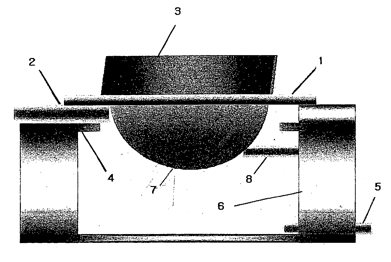
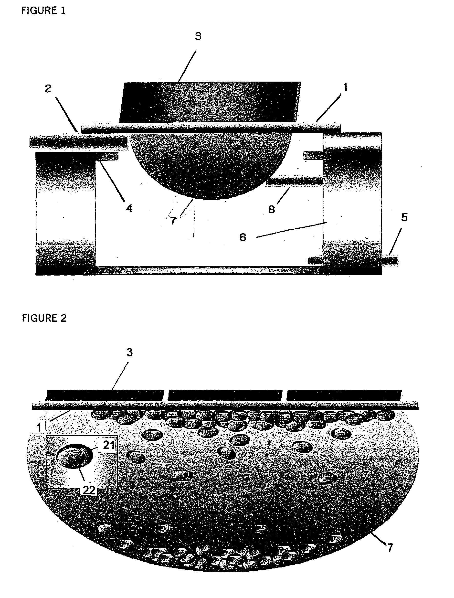
[0040]FIG. 1 illustrates an apparatus of separating cells using magnets and droplet type cell suspension according to a preferred embodiment of the present invention.

[0041]Referring to FIG. 1, an apparatus of separating cells using magnets and droplet type cell suspension according to a preferred embodiment of the present invention includes a droplet type cell suspension forming part 1 for forming a droplet type cell suspension under a lower part of the droplet type cell suspe...


PUM

PropertyMeasurementUnit
diameteraaaaaaaaaa
diameteraaaaaaaaaa
diameteraaaaaaaaaa

Abstract

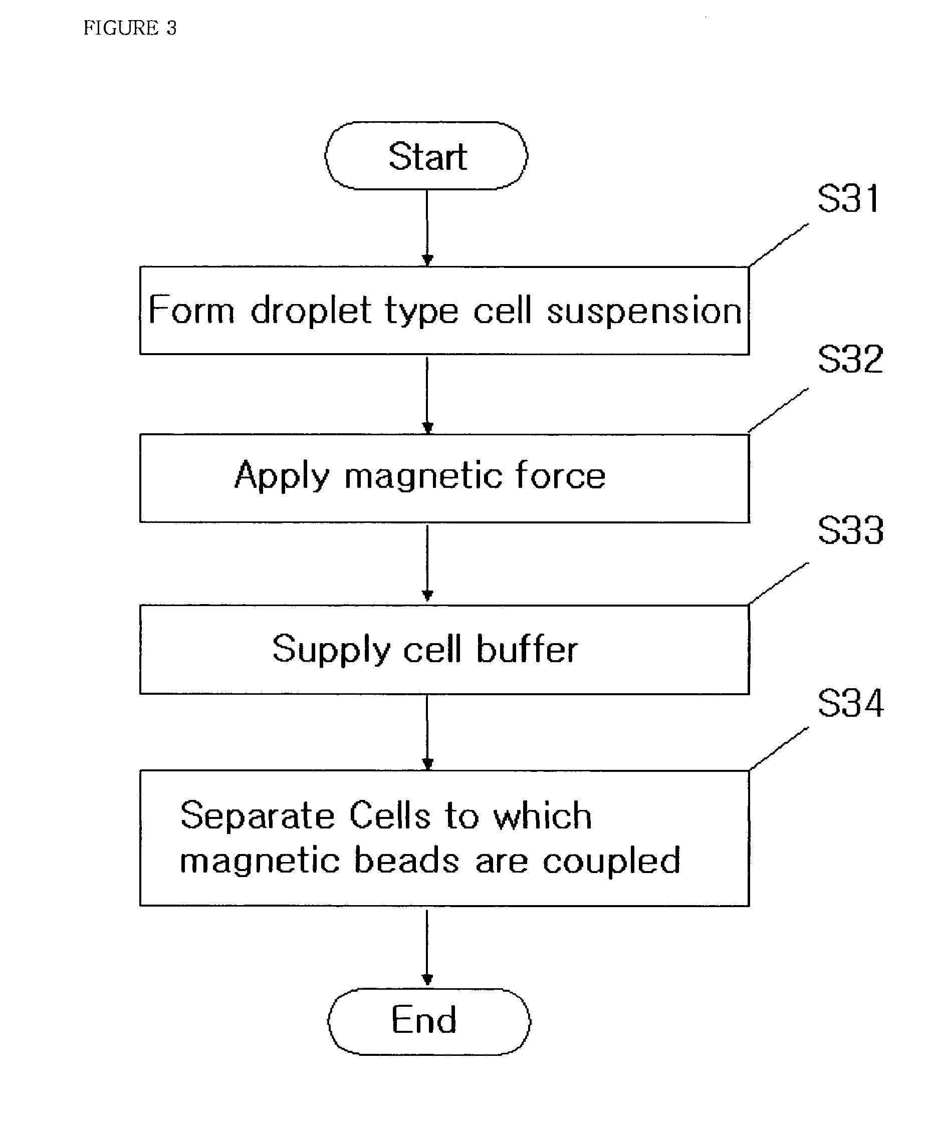
Disclosed are methods and apparatuses for separating cells using magnets and droplet type cell suspension according to the present invention, which may effectively separate cells by forming droplet type cell suspension with cell suspension sample containing cells to which magnetic beads are coupled and applying magnetic force to the droplet type cell suspension.The apparatus of separating cells according to the present invention includes: a droplet type cell suspension forming part for forming a droplet type cell suspension under a lower part of the droplet type cell suspension forming part with cell suspension sample containing cells to which magnetic beads are coupled; a cell suspension inlet for supplying the droplet type cell suspension forming part with the cell suspension sample; a magnet for applying magnetic force to the droplet type cell suspension; a cell buffer inlet for supplying the droplet type cell suspension with cell buffer; and a temperature maintaining part for maintaining a temperature of the droplet type cell suspension.

Description

CROSS-REFERENCE TO RELATED APPLICATION[0001]The entire disclosure of Korean Patent Application No. 10-2004-0025421 filed on Apr. 13, 2004 including specification, claims, drawings and summary, is incorporated herein by reference in its entirety.BACKGROUND OF THE INVENTION[0002]1. Field of the Invention[0003]The present invention relates to methods and apparatuses of separating cells, and more particularly to methods and apparatuses of separating cells using magnets and droplet type cell suspension, which may effectively separate cells by forming droplet type cell suspension with cell suspension sample containing cells to which magnetic beads are coupled and applying magnetic force to the droplet type cell suspension.[0004]2. Description of the Related Art[0005]Methods of separating cells in the related art are classified into two methods. Specifically, a first method is to separate cells using a tube type apparatus of separating using magnetic force and gravitation and a second meth...

Claims


Application Information

Patent Timeline
Patent Type & Authority Patents(United States)
IPC IPC(8): C12M1/42C12M1/26C12M1/34C12N1/02
CPCC12N1/02C12M47/04C12M47/02C12M1/42
Inventor KIM, YOUNG-HOJU, BYEONG-KWONYUN, SEOKKANG, YU-RIPAEK, KYEONG-KAPLEE, JIN-WOOKIM, BYUNG KYUPARK, JONG OH
Owner KOREA INST OF SCI & TECH
Learn More