Radiation treatment apparatus

Inactive Publication Date: 2007-03-13
HITACHI LTD
View PDF18 Cites 92 Cited by
  • Summary
  • Abstract
  • Description
  • Claims
  • Application Information

AI Technical Summary

Benefits of technology

[0015]In the radiation treatment apparatus according to the present invention, it is preferable that the turning axis be situated in parallel with a plane defined by the orbit, in order to maximize the range of movement of the radiation generating unit. In addition, it is preferable that the guide be supported by the support member at one portion on the turning axis, or at two portions on the turning axis on both sides of the isocenter.
[0016]In the radiation treatment apparatus according to the present invention, it is preferable that the guide be provided with a movable member that rotatably supports the radiation generating unit on two rotational axes crossing each other, thereby to apply radiation to an object of radiation apart from the isocenter. It is preferable that the movable member be disposed on at least a pair of rails provided on the guide in order to improve the reproducibility of the angle of application of radiation.
[0026]In the radiation treatment apparatus according to the present invention, it is preferable that the imager be an X-ray CT scanner, in order to increase the amount of information of the acquired radiation transmission image.
[0027]In the radiation treatment apparatus according to the present invention, in order to reduce the weight of the radiation generating unit mounted on the guide, it is preferable to provide a microwave source positioned apart from the movable member and the guide, and to supply microwaves to the radiation generating unit via a waveguide.

Problems solved by technology

Consequently, it is difficult to precisely position the head that emits radiation.
Moreover, the adjustment of position of the head is complex, and the reproducibility of the angle of application of radiation is low.
In these conventional radiation treatment apparatuses, the radiation cannot precisely be applied, and thus the amount of radiation on parts other than the object of radiation increases.

Method used


Image

  • Radiation treatment apparatus
  • Radiation treatment apparatus
  • Radiation treatment apparatus

Examples


first embodiment

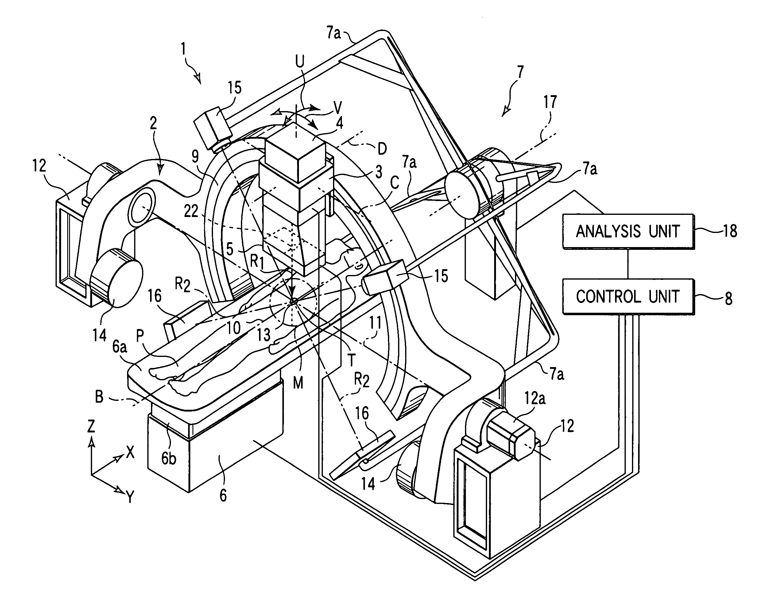
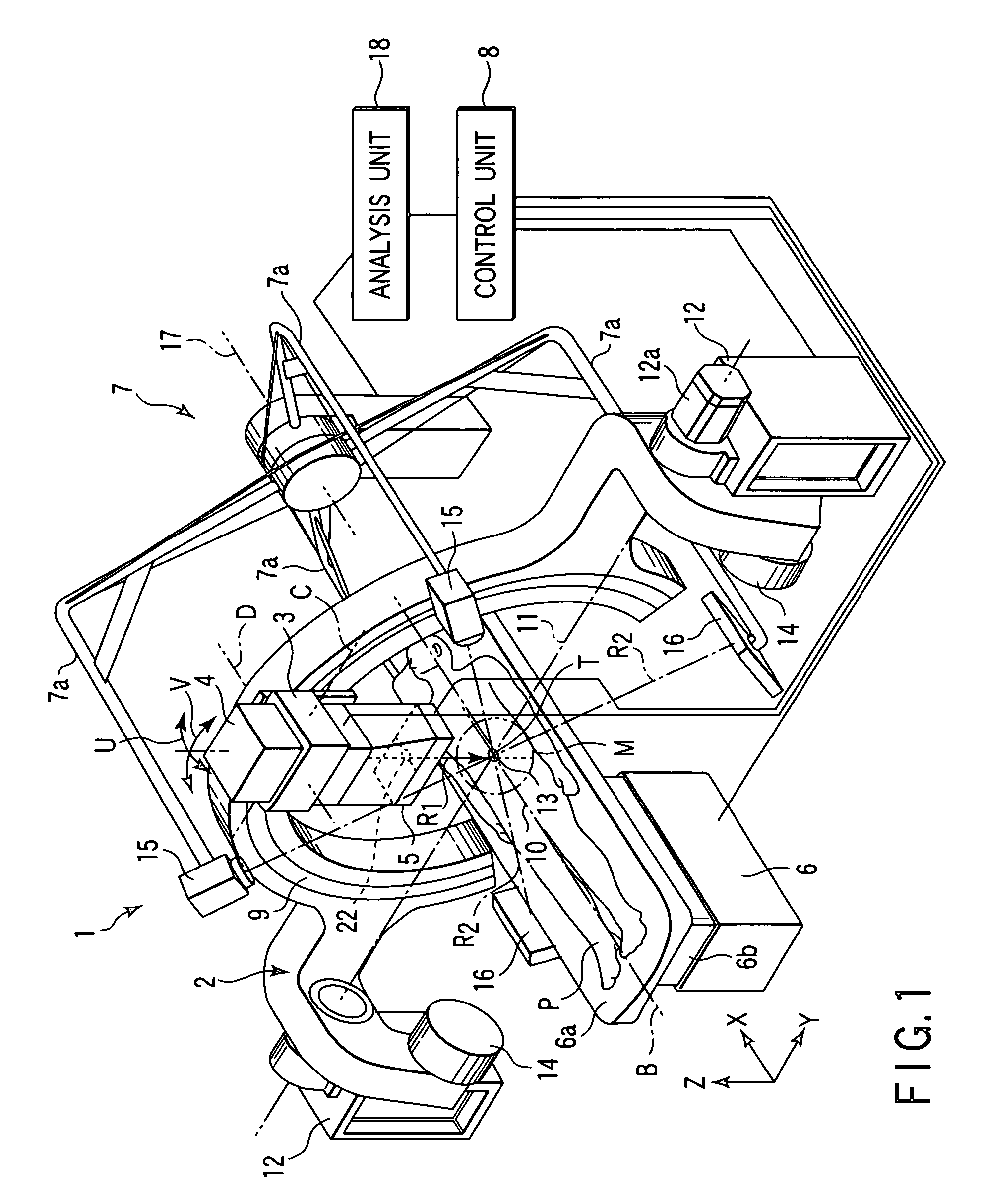
[0078]A radiation treatment apparatus 1 according to the present invention will now be described with reference to FIGS. 1 and 2. The radiation treatment apparatus 1 shown in FIG. 1 comprises a radiation generating unit 4, a variable collimator 5, a manipulator 2, a movable table 6, a diagnosis imager 7, and a control unit 8.

[0079]The radiation generating unit 4 emits an X-ray R1 as radiation for treatment. The X-ray R1 is generated by accelerating electrons emitted from an electron gun through an accelerator, and making the accelerated electrons impinge upon a target.

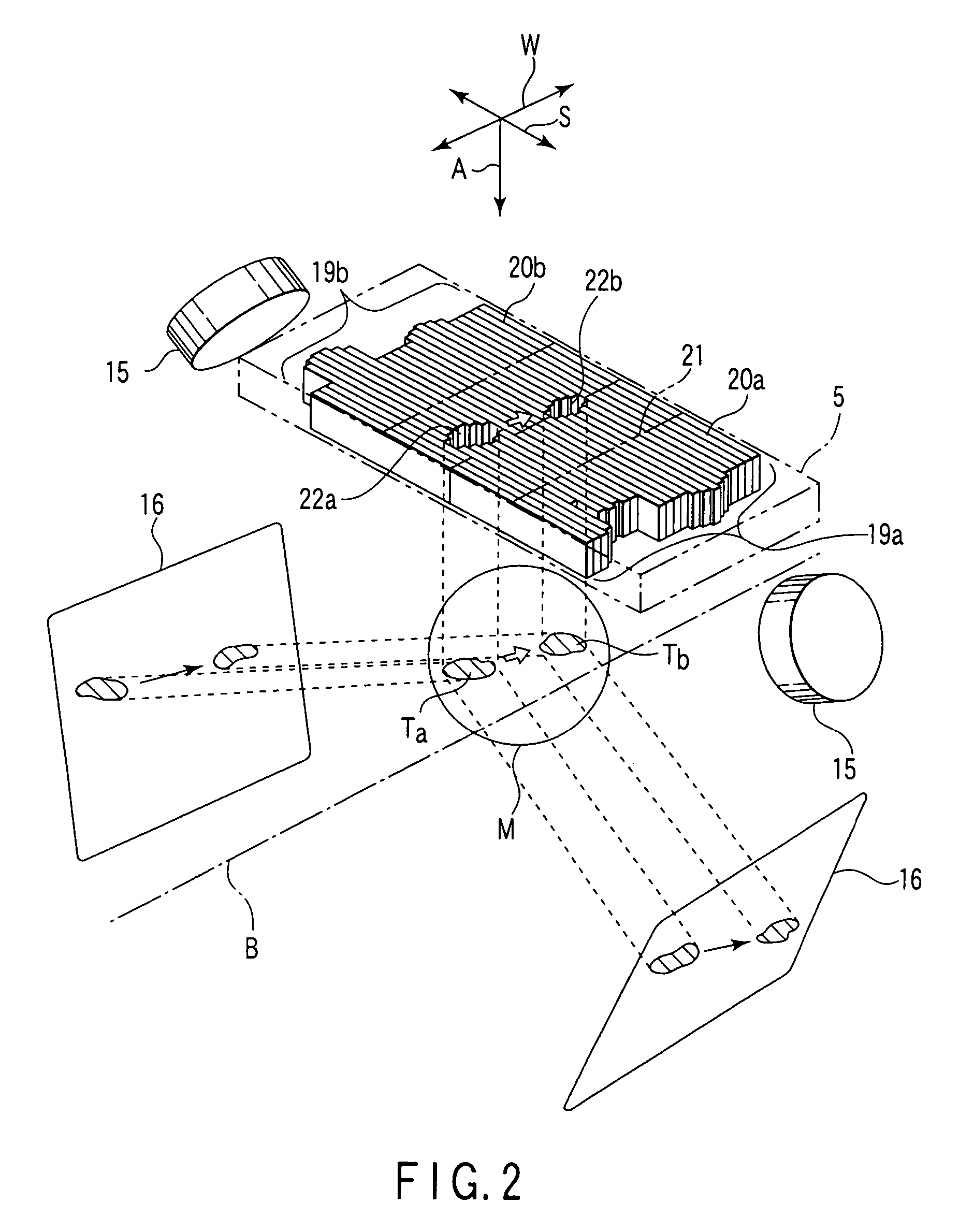
[0080]The variable collimator 5 is attached to an emission port of the radiation generating unit 4. Accordingly, the generated X-ray R1 is emitted through the variable collimator 5. As is shown in FIG. 2, the variable collimator 5 includes two slide groups 19a, 19b. Each slide group 19a, 19b comprises a number of slides 20a, 20b, which are movable in an S-direction perpendicular to an A-direction in which the X-ray R1 ...

second embodiment

[0099]In order to reduce the weight of the radiation generating unit 4 mounted on the movable member 3, it is possible to provide a microwave generating unit, e.g. a Klystron, on a base portion of the manipulator 2 and to guide microwaves from the Klystron to an accelerator built in the radiation generating unit 4 with use of a waveguide. A concrete example of this case will be described below as the invention.

[0100]A radiation treatment apparatus according to the second embodiment of the invention will now be described with reference to FIGS. 3 to 6. The same parts as those of the radiation treatment apparatus 1 of the first embodiment are denoted by same reference numerals, and a description thereof is omitted.

[0101]In a radiation treatment apparatus 41 shown in FIG. 3, like the radiation treatment apparatus 1 shown in FIG. 1, a guide 9 is rotated about a turning axis 11 that horizontally passes through an isocenter 13. The guide 9 is supported on support members 12 on both sides ...


PUM


Abstract

A radiation treatment apparatus includes a guide and a support member. The guide moves a radiation generating unit along an orbit with a predetermined radius such that an X-ray emitted from the radiation generating unit may cross an isocenter. The support member rotates the guide about a turning axis passing through the isocenter. The radiation generating unit is moved along a spherical plane by the guide and the support member and applies the X-ray toward the isocenter in multiple directions.

Description

CROSS-REFERENCE TO RELATED APPLICATIONS[0001]This is a Continuation Application of PCT Application No. PCT / JP02 / 08504, filed Aug. 23, 2002, which was not published under PCT Article 21(2) in English.[0002]This application is based upon and claims the benefit of priority from the prior Japanese Patent Applications No. 2001-254891, filed Aug. 24, 2001; No. 2001-254892, filed Aug. 24, 2001; and No. 2002-022253, filed Jan. 30, 2002, the entire contents of all of which are incorporated herein by reference.BACKGROUND OF THE INVENTION[0003]1. Field of the Invention[0004]The present invention relates to a radiation treatment apparatus having a radiation generating unit, which is movable around an object of radiation, and applying radiation to the object of radiation in multiple directions.[0005]2. Description of the Related Art[0006]For example, a radiation treatment apparatus for use in radiation treatment comprises a linear accelerator for generating radiation and a positioning device for...

Claims


Application Information

Patent Timeline
IPC IPC(8): H05G1/02A61B19/00A61N5/10
CPCA61N5/10A61N5/1042A61N5/1047A61B6/548A61N5/1081A61N5/1082A61N5/1049A61B2019/207A61N5/1067A61N2005/1061A61B2090/101
Inventor MIHARA, KAZUMASAHARA, KENJIYAMASHITA, ICHIROWAKAMOTO, IKUOKAMINO, YUICHIRO
Owner HITACHI LTD
Why Eureka
Try Eureka