
Method and apparatus for optically scanning a scene

a scene and optical scanning technology, applied in the direction of instruments, using reradiation, transportation and packaging, etc., can solve the problems of two separate prisms, a substantial structural space for prisms, and a large space for prisms, so as to achieve detection or scanning, production and assembly economic effects

Inactive Publication Date: 2007-03-06
A D C AUTOMOTIVE DISTANCE CONT +1
View PDF42 Cites 9 Cited by
  • Summary
  • Abstract
  • Description
  • Claims
  • Application Information

AI Technical Summary

Benefits of technology

"The invention is a method and apparatus for optically scanning a scene using a scanning beam that is moved or scanned over the scene. The apparatus includes a transmitting part for emitting the scanning beam and a receiving part for detecting a reflected beam from the scanning beam on the scene. The technical effects of the invention include simplifying and economizing the optical scanning process, making it more compact and space-saving, and achieving a larger angular range of scanning without gaps between scan lines. The invention also includes a prism with multiple side surfaces that reflect the scanning beam in different directions, and a lens arrangement for focusing or collimating the scanning beam onto the scene. The receiving part of the apparatus can also include a photodetector instead of a beam source."

Problems solved by technology

A substantial disadvantage of the known apparatus and method is that two separate prisms are required for achieving the horizontal and vertical deflection or scanning of the scanning beam.
These two prisms require a substantial structural space and are each subject to operational interferences or malfunctions.
This known method and apparatus, however, have the disadvantage, that each one of the mirrored side surfaces of the polygon mirror must be relatively large in order to achieve a deflection of the entire laser beam over the required angular range of the scanning field.

Method used


Image

  • Method and apparatus for optically scanning a scene
  • Method and apparatus for optically scanning a scene
  • Method and apparatus for optically scanning a scene

Examples


first embodiment

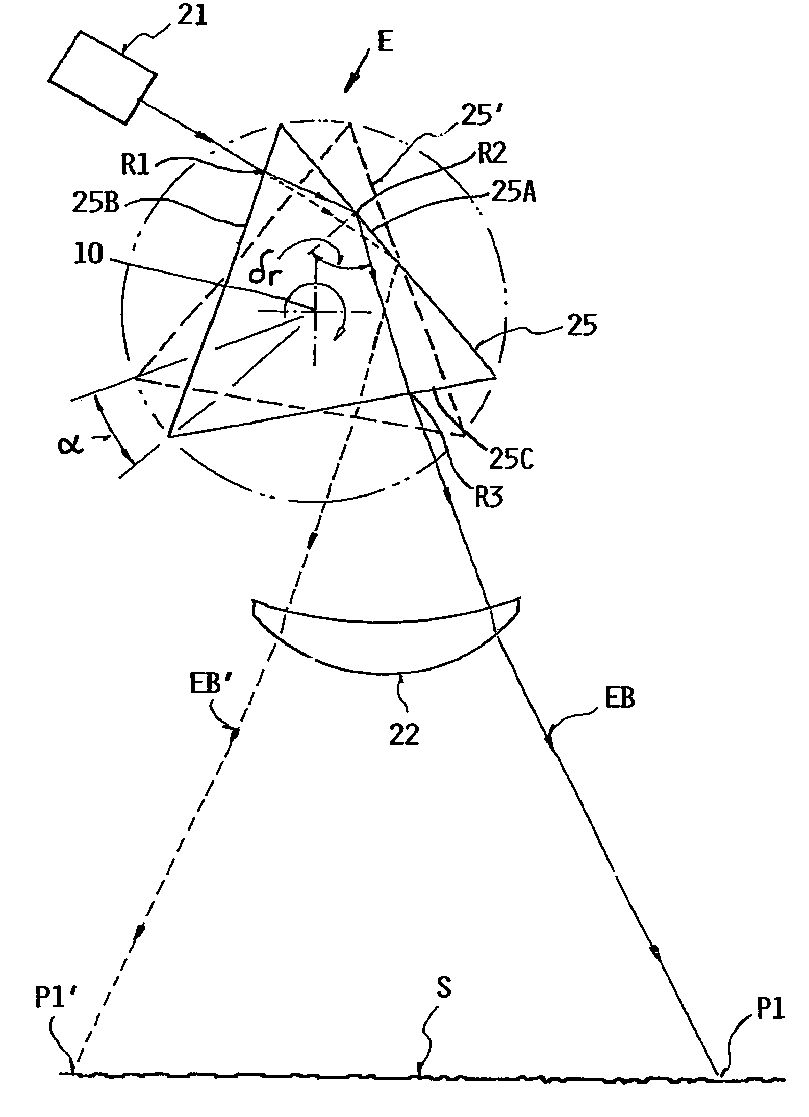
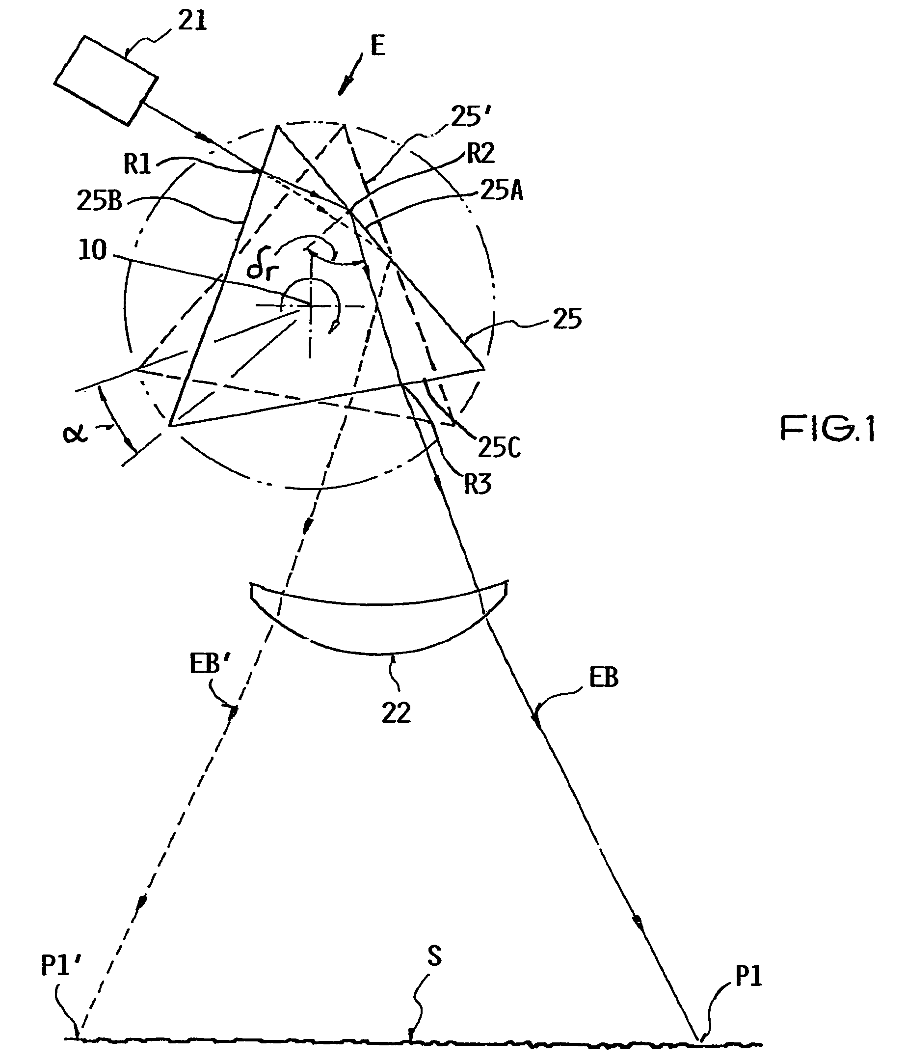
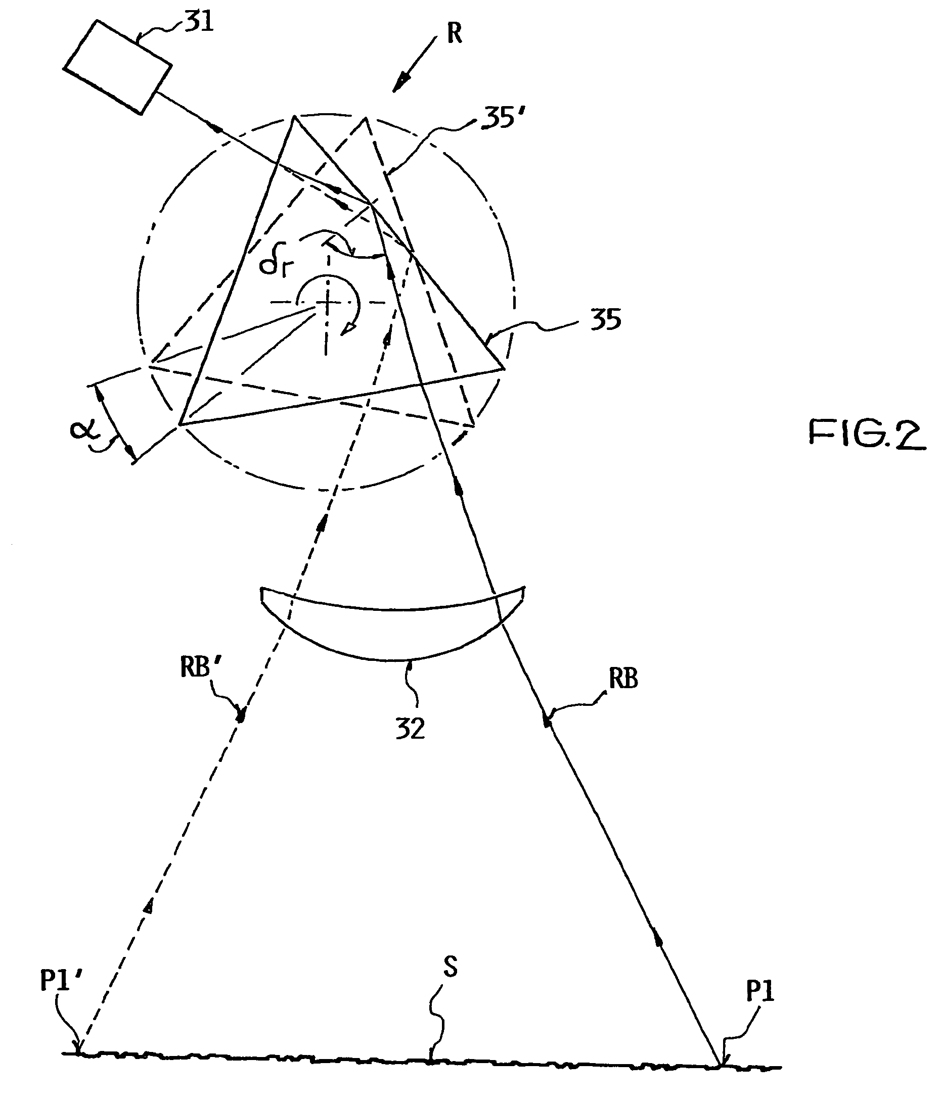
[0029]an optical scanning apparatus according to the invention will now be described in detail with reference to FIG. 1 showing the emitting part E, and FIG. 2 showing the receiving part R, of the overall apparatus. This apparatus can be used for carrying out the general embodiment of the inventive method.

[0030]As shown in FIG. 1, the emitting part E of the apparatus includes a light source 21, for example embodied as an infrared laser diode, a first prism 25 with an equilateral triangular cross-section bounded by three side surfaces 25A, 25B and 25C, and a lens arrangement 22 embodied as a Fresnel lens, for example. The light source 21, which is arranged at a fixed position with a fixed orientation, emits an emitted light beam EB in a direction toward the prism 25. Namely, the prism 25 is interposed in the beam path of the emitted light beam EB, so that the emitted beam EB penetrates into the body of the prism 25.

[0031]Thereby, for example, the emitted beam EB from the light source...


PUM

PropertyMeasurementUnit
tilt anglesaaaaaaaaaa

Abstract

A light beam is deflected by refraction and total internal reflection through a first prism, and projected through a first lens onto a scene that is to be scanned. The prism rotates, which varies the deflection angle and scans the beam across the scene along a scan line. Preferably, the successive side surfaces of the prism have different tilt angles relative to the rotation axis, so as to respectively deflect the beam in different deflection planes which cause successive scan lines of the beam across the scene. The emitted beam gives rise to a reflected beam from the scene, which is received through a second lens and deflected onto a photodetector through a second prism congruent to and rotating synchronously with the first prism. This apparatus is suitable as a laser scanning device for an object recognition system or a spacing distance regulation system of a motor vehicle.

Description

CROSS-REFERENCE TO RELATED APPLICATIONS[0001]This application is a Continuation-In-Part under 35 U.S.C. §120 of PCT International Application PCT / DE02 / 02675, filed on Jul. 18, 2002, and PCT International Application PCT / DE02 / 03028, filed on Aug. 9, 2002, both of which designated the United States, and both of which were published in a language other than English. The entire disclosures of both of these PCT International Applications are incorporated herein by reference.PRIORITY CLAIM[0002]Through the above identified PCT International Applications, this application is based on and claims the priority under 35 U.S.C. §119 of German Patent Application 101 35 107.0, filed on Jul. 19, 2001, and German Patent Application 101 41 363.7, filed on Aug. 23, 2001. The entire disclosures of both of the German Priority Applications are incorporated herein by reference.FIELD OF THE INVENTION[0003]The invention relates to a method as well as an apparatus for scanning a scene or image with an optic...

Claims


Application Information

Patent Timeline
Patent Type & Authority Patents(United States)
IPC IPC(8): G01N21/55G01S17/931B60Q1/52G01S7/481G01S17/42G02B26/10
CPCG01S7/4817G02B26/108G02B26/101G01S17/936G01S17/42G01S17/931
Inventor SCHANZ, HOLGERKRAUS, ROBERTMEHR, WILFRIED
Owner A D C AUTOMOTIVE DISTANCE CONT
Learn More