Positioning mechanism, exposure apparatus and device manufacturing method
a technology of exposure apparatus and manufacturing method, which is applied in the direction of piezoelectric/electrostrictive device details, printers, instruments, etc., can solve the problems of dust creation, damping effect change, dust creation, etc., and achieve the effect of small dust creation and small degassing
- Summary
- Abstract
- Description
- Claims
- Application Information
AI Technical Summary
Benefits of technology
Problems solved by technology
Method used
Image
Examples
first embodiment
[First Embodiment]
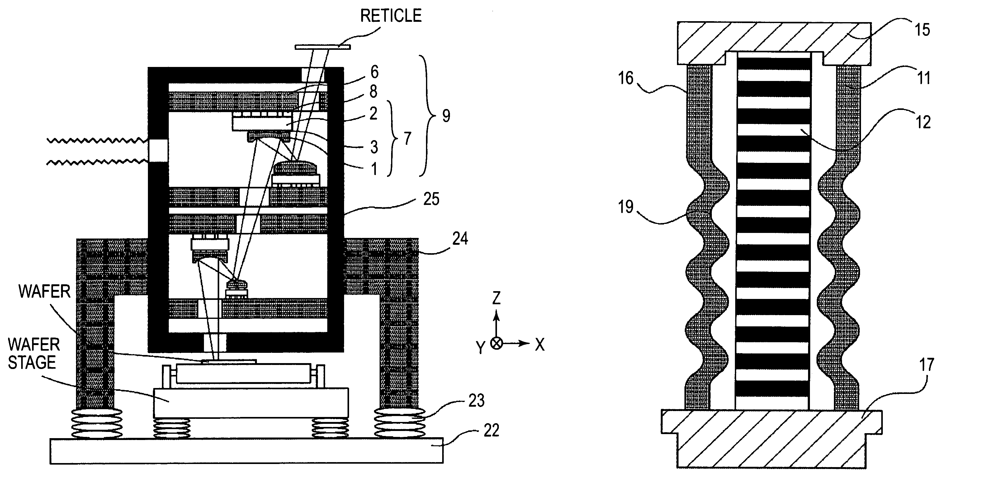
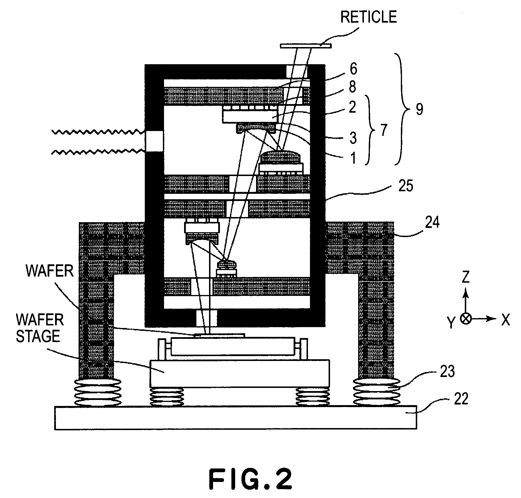
[0063]FIG. 2 is a schematic view of a general structure of an exposure apparatus having incorporated therein holding means 3 for an optical element 1 and an attitude adjusting mechanism (adjusting system and positioning system) 8 according to the present invention.
[0064]As an example, this exposure apparatus is a reduction projection exposure apparatus (EUV exposure apparatus) using extreme ultraviolet light (EUV light) having a wavelength of bout 10–15 nm, being yet shorter than the ultraviolet ray. It functions to transfer, by exposure, a pattern formed on a reticle (original) placed on a reticle stage onto a wafer (object to be exposed) placed on a wafer stage. Here, the reticle stage and the wafer stage are driven in synchronism with each other in accordance with the projection magnification (¼ in this example), by which the pattern of the reticle is transferred to the wafer. The projection optical system comprises four mirrors, in this example. However, the pr...
second embodiment
[Second Embodiment]
[0086]In the second embodiment, in addition to a metal bellows 19 (hereinafter, “first metal bellows”), there is a second metal bellows 16 which is disposed outside the first metal bellows 19 and is provided concentrically with the first metal bellows 19. It is not necessary that these bellows have exactly registered centers in a strict sense. The centers of them may be deviated by an amount not greater than ⅕ (more preferably, not greater than 1 / 10) of a radius of a circumscribed circle in the section of either one of the two bellows. An attenuating material may be sealingly accommodated in the clearance between the first and second metal bellows and, in that occasion, an attenuating element can be added without direct contact to the piezoelectric device. FIG. 7 illustrates a sectional view of a piezoelectric actuator having an attenuating material sealingly accommodated therein, the attenuating material being out of contact with a piezoelectric device, such as d...
third embodiment
[Third Embodiment]
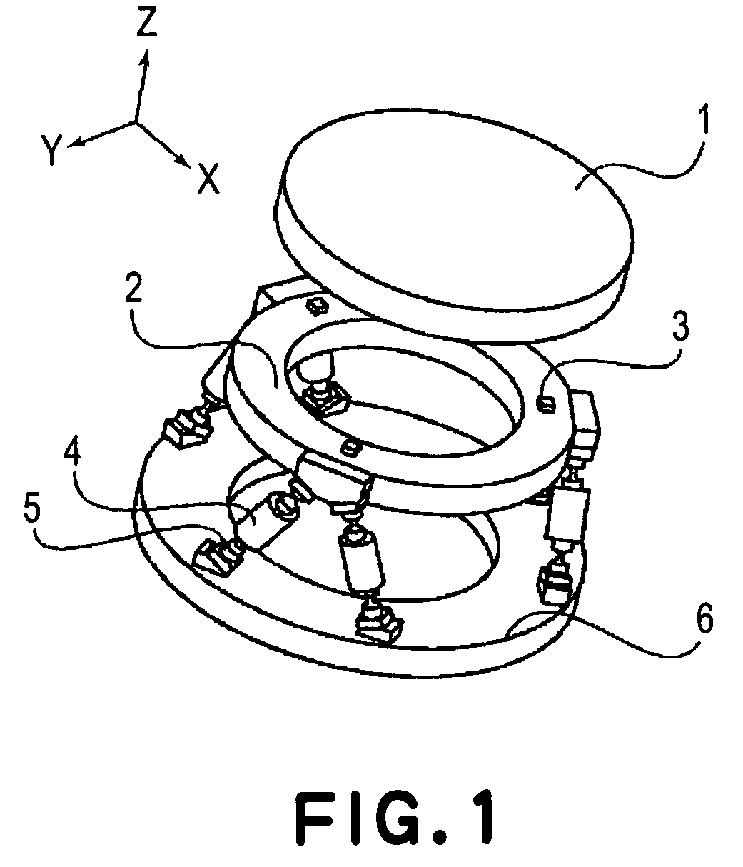
[0091]FIG. 10 is a perspective view of a general structure of a differential type parallel linkage mechanism according to a third embodiment of the present invention. In FIG. 10, some components such as optical element and holding means shown in FIG. 1, are not illustrated.
[0092]The movable portion 7 has a ring-like shape in FIG. 10, but it may have a circular shape like a mirror or lens (optical element), a polygonal shape (e.g. triangular or rectangular), a combined shape of arcuate (e.g. fan shape) and straight, or a combined shape of arcs having different curvature radii. Any other shape is usable, as a matter of course. As an alternative, the structure may be arranged so that the optical element 1 is indirectly connected to the movable portion 7 through the holding means.
[0093]Mounted between the movable portion 7 and the fixed block 6 are three integral type differential linkage mechanisms 36 which are disposed approximately equidistantly along the circumfere...
PUM
| Property | Measurement | Unit |
|---|---|---|
| wavelength | aaaaa | aaaaa |
| a wavelength | aaaaa | aaaaa |
| wavelength | aaaaa | aaaaa |
Abstract
Description
Claims
Application Information
 - R&D Engineer
- R&D Manager
- IP Professional
- Industry Leading Data Capabilities
- Powerful AI technology
- Patent DNA Extraction
Browse by: Latest US Patents, China's latest patents, Technical Efficacy Thesaurus, Application Domain, Technology Topic, Popular Technical Reports.
© 2024 PatSnap. All rights reserved.Legal|Privacy policy|Modern Slavery Act Transparency Statement|Sitemap|About US| Contact US: help@patsnap.com


