
Recirculation structure for a turbocompressor

a turbocompressor and recirculation structure technology, which is applied in the direction of turbine/propulsion air intake, motors, air transportation, etc., can solve the problems of reducing the efficiency level of the compressor, affecting so as to improve the surge margin, reduce and improve the efficiency of the compressor.

Inactive Publication Date: 2007-03-06
MTU AERO ENGINES GMBH
View PDF19 Cites 26 Cited by
  • Summary
  • Abstract
  • Description
  • Claims
  • Application Information

AI Technical Summary

Benefits of technology

[0008]In view of the disadvantages of the state of the art solutions, the object of the invention is to provide a recirculation structure for turbo-compressors that will enable a substantial enhancement of the surge margin, and thus a clear expansion of the stable operating range, without a significant reduction of the efficiency of the compressor.
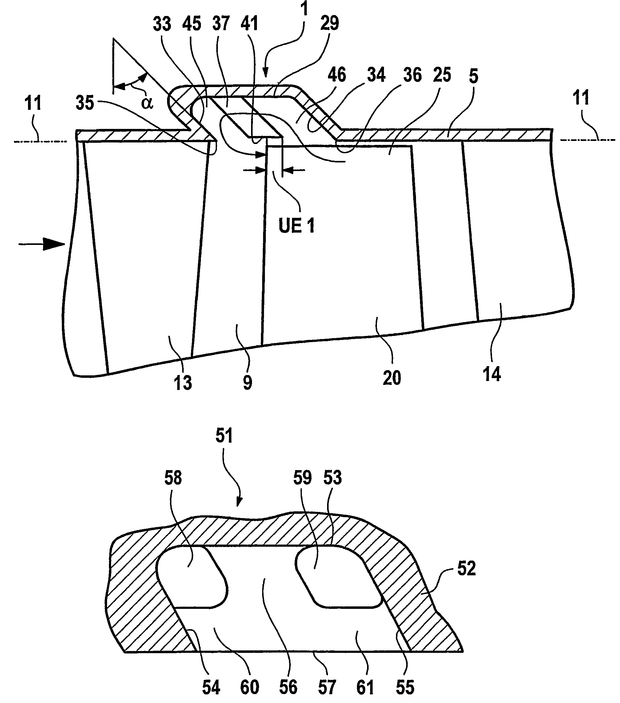
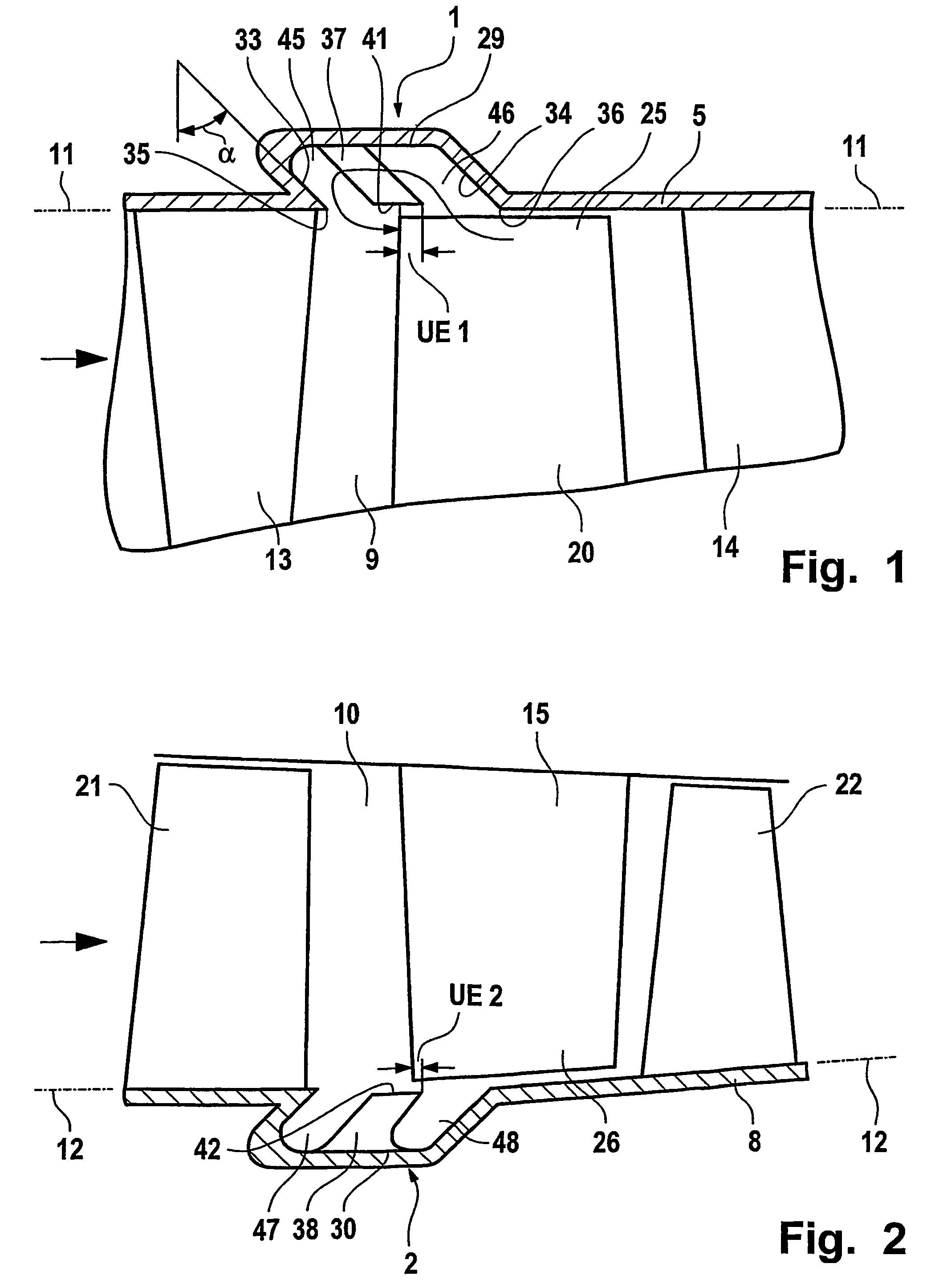
[0009]The essence of the invention is to have the tips of the guide vanes that face the annular chamber lie on or near the contour of the main flow channel, and axially overlap the free ends of the blades or axially border the area of the free ends of the blades. In this manner, annular elements with contact coatings, etc. can be eliminated. The above-cited patent specifications show that up to now the professional world has consistently tried to design recirculation structures that will be smooth, without gaps, and closed over the largest possible axial range, up to the main flow channel, i.e. up to the so-called annular chamber, in order to effect an extension of the contours of the main flow channel that will be as favorable in terms of flow and loss as possible. The invention, in contrast, leads to gaps, fissured surfaces, etc., and thus would appear to be disadvantageous and inexpedient. Test have shown, however, that the recirculation structure of the invention is superior to known solutions in terms of both enhancing the surge margin and improving the level of efficiency. This can be explained in aerodynamic terms in that the free, informal design of the recirculation flow in the open annular chamber with free-standing guide vanes and circumferential flow links is more important than the greatest possible gap-free extension of the contour of the main flow channel. The absence of a closed ring has the further advantages that no contact or intake coating of the guide vanes is necessary, and radial space and weight are saved, resulting in structural mechanical advantages. However, a defined control of the recirculation flow—without annular elements—is achieved only if the free edges of the guide vanes run relatively close to the edges of the blades, partially overlapping them axially, or at least lying adjacent to their space. Only in this way can a compact “casing treatment” that is suitable for use in a compressor ultimately be achieved.

Problems solved by technology

The primary disadvantage of known “casing treatments” is that, although they do increase the surge margin, they also reduce the efficiency level of the compressor.
These are not taken into consideration here, however, because the grooves are not connected to one another in these versions; hence no circumferential flow comparison is possible.
Of further disadvantage is the large volume of the annular chamber (16) in relation to the blade dimensions.
This type of embodiment is neither aerodynamically nor constructively suitable for a turbo-compressor.
The invention, in contrast, leads to gaps, fissured surfaces, etc., and thus would appear to be disadvantageous and inexpedient.
This is due to the fact that the tips of the blades may be damaged by brushing against something, especially against hard, inflexible guide vane tips.

Method used


Image

  • Recirculation structure for a turbocompressor
  • Recirculation structure for a turbocompressor
  • Recirculation structure for a turbocompressor

Examples


Embodiment Construction

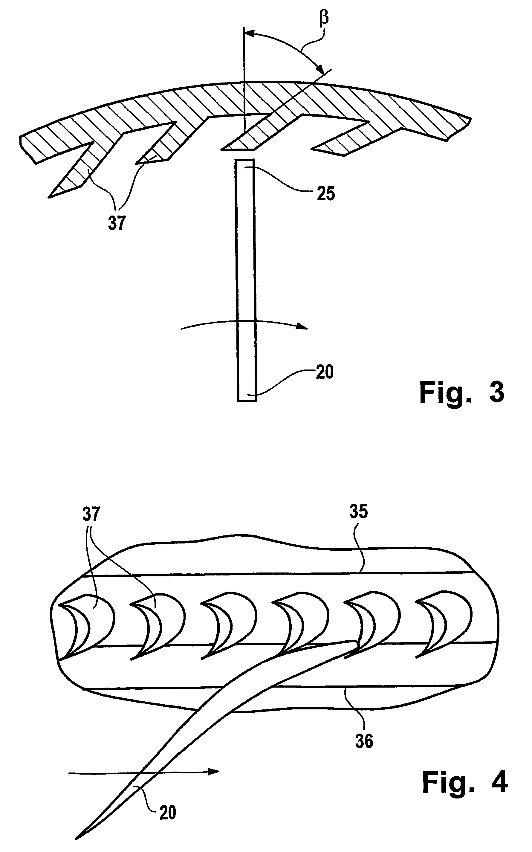
[0022]The recirculation structure 1 according to FIG. 1 is integrated into the casing 5 of a turbo-compressor, and thus is to be referred to as a “casing treatment”. The direction of flow in the bladed main flow channel 9 is indicated on the left by an arrow, thus it flows from left to right. In the area shown here, the flow first strikes a vane ring 13, then a rotating blade ring 20, and finally another vane ring 14. The radial outer contour 11 of the main flow channel 9 corresponds to the inner contour of the casing 5, and for purposes of clarification is continued here by dotted / dashed lines to the left and right of the actual illustration. The static recirculation structure 1 operates in conjunction with the rotating blade ring 20, and lies for the most part axially in front of said blade ring, i.e. upstream. The annular chamber 29, which together with the guide vanes 37 forms the recirculation structure 1, borders the main flow channel 9 radially from the outside, and is open t...


PUM


Abstract

A recirculation structure for turbo-compressors has an annular chamber that is positioned in the area of the free blade ends of a rotating blade ring and that radially borders the main flow channel, and has a multitude of guide vanes arranged in the annular chamber and distributed around its circumference. The annular chamber enables the passage of air flow in the forward and / or rear areas, and the guide vanes are firmly fixed to at least one wall of the annular chamber and otherwise are designed to be free-standing. The tips of the guide vanes that face the annular chamber extend along and / or near the contour of the main flow channel, and axially overlap the free blade ends or axially border the area of the free blade ends.

Description

BACKGROUND AND SUMMARY OF THE INVENTION[0001]This invention relates to a recirculation structure for turbo-compressors, a turbo-compressor, an aircraft engine, and a stationary gas turbine.[0002]Recirculation structures for turbo-compressors have been known in the art for quite a long time, and in the trade are generally referred to as “casing treatments”. Their primary function is to increase the aerodynamically stable operating range of the compressor, wherein the so-called surge margin is shifted to higher compressor pressures, i.e. to a higher compressor load. The failures that are responsible for localized stalling and ultimately for the surging of the compressor occur on the casing side at the ends of the rotating blades of one or more compressor stages, and on the hub side at the ends of the vanes that lie radially inside, because in these areas the aerodynamic load is the highest. By recirculating the “air particles” that circulate between the blade tips at blade speed, and ...

Claims


Application Information

Patent Timeline
Patent Type & Authority Patents(United States)
IPC IPC(8): F01D11/08F01D5/14F02C7/04F04D27/02F04D29/54
CPCF01D5/145F01D11/08F04D29/164F04D27/0207F04D29/545F04D29/685F04D29/526F05D2220/40Y02T50/60F04D29/321
Inventor SEITZ, PETER
Owner MTU AERO ENGINES GMBH
Learn More