
LLC series resonant converter and the driving method for the synchronous rectification power switches thereof

a technology of synchronous rectification and resonant converter, which is applied in the direction of electric variable regulation, process and machine control, instruments, etc., can solve the problems of circuit not being able to operate properly and safely, and achieve the effect of ensuring safe and reliable operation

Active Publication Date: 2007-02-27
DELTA ELECTRONICS INC
View PDF3 Cites 95 Cited by
  • Summary
  • Abstract
  • Description
  • Claims
  • Application Information

AI Technical Summary

Benefits of technology

[0020]It is an object of the present invention to provide an LLC series resonant converter, and a driving method for the synchronous rectification power switches to obtain suitable driving signals, which allow the power MOSFETs to substitute the rectification diodes, therefore synchronous rectification in the LLC series resonant converter can be implemented, and operation under any conditions can be guaranteed in safe and reliability.
[0023]The present invention is based on the relation in quantity between the operating frequency of the LLC series resonant converter and the series resonant frequency of the resonant network, and based on the diving signals of the power switches, so as to provide the driving signals of the synchronous rectification power switches. As a result, the power MOSFET can replace the rectification diodes and implement the synchronous rectification in the LLC series resonant converter, and further assure the safe and reliable operation in any operation condition.

Problems solved by technology

Otherwise, the output terminal of the converter would transport power to the primary side of the converter, and the circuit would not be able to operate properly and safely.

Method used


Image

  • LLC series resonant converter and the driving method for the synchronous rectification power switches thereof
  • LLC series resonant converter and the driving method for the synchronous rectification power switches thereof
  • LLC series resonant converter and the driving method for the synchronous rectification power switches thereof

Examples


Embodiment Construction

[0031]A following preferred embodiment is taken to describe the LLC series resonant converter (SRC).

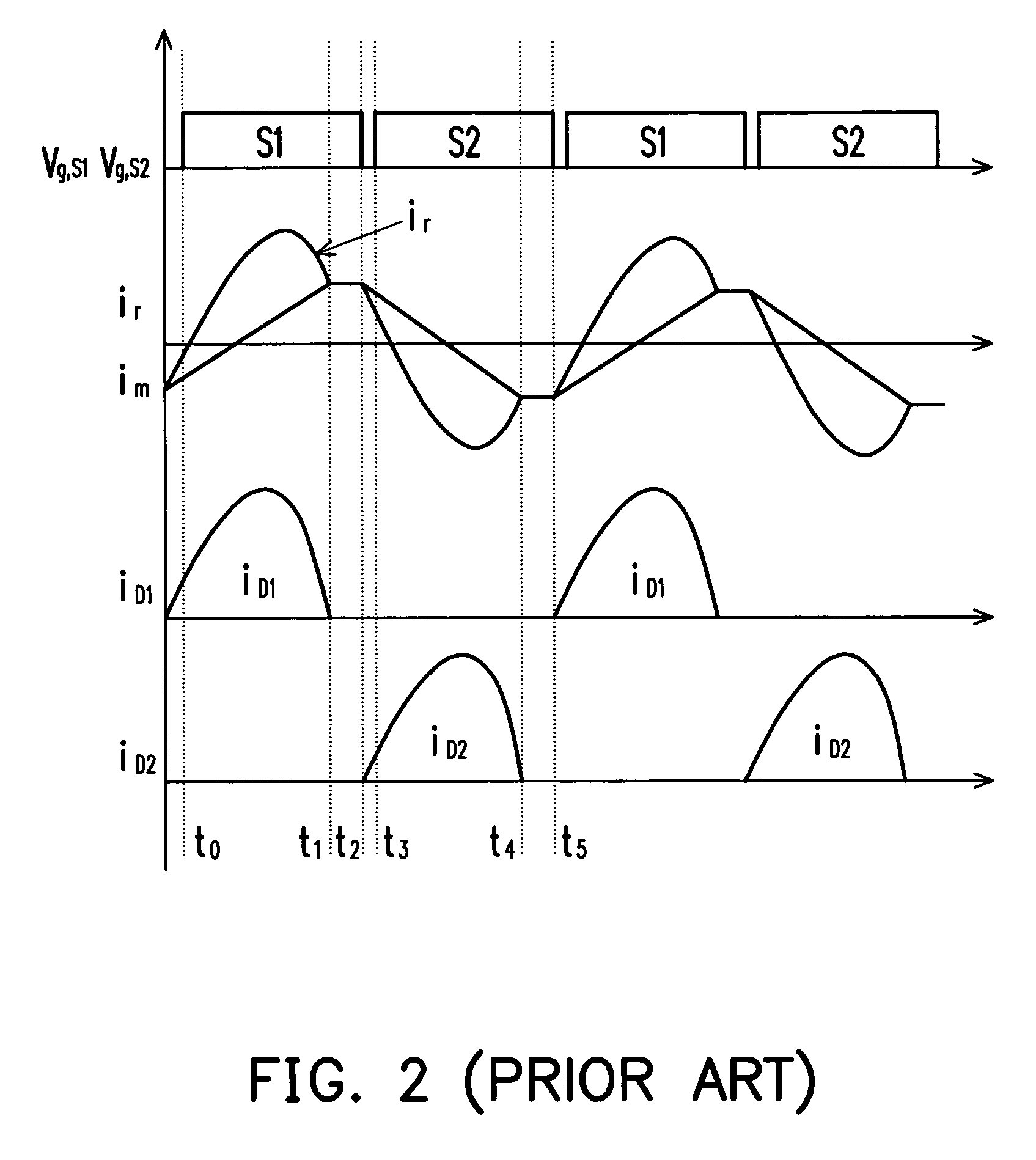
[0032]According to the operating waveform of the LLC series resonant converter, as shown in FIG. 2, when the output rectification current irec has a dead time, the conducting time of the rectification diodes D1 and D2 is a half time period 1 / (2fs) of the LLC series resonant converter, but it is determined by the values of Ls and Cs. When a range of the input voltage or the output voltage changes, provided fm1 and D2 does not change thereafter. The change is just the dead time of the rectification current irec, which is the time interval from t1 to t2 or from t4 to t5. When the operating frequency is higher than fs, the output rectification current irec does not have a dead time. Therefore, the conducting times of D1 and D2 are respectively corresponding to the conducting times of the power switches S1 and S2.

[0033]In view of the above, the preferred embodiment adopts a self-adaptive s...


PUM


Abstract

An LLC series resonant converter and a driving method for the synchronous rectification power switches thereof are provided. The LLC series resonant converter includes a bridge circuit, a resonant network, a transformer, a rectification circuit, and a frequency adjustment controller. The bridge circuit includes at least one pair of power switches. The power switches drive the resonant network. The rectification circuit includes at least one pair of synchronous rectification power switches. The synchronous rectification power switches and the power switches have a mapping relation between them. The frequency adjustment controller provides driving signals to the synchronous rectification power switches in response to the operating frequency of the LLC series resonant converter and the series resonant frequency of the resonant network, to implement synchronous rectification in the LLC series resonant converter.

Description

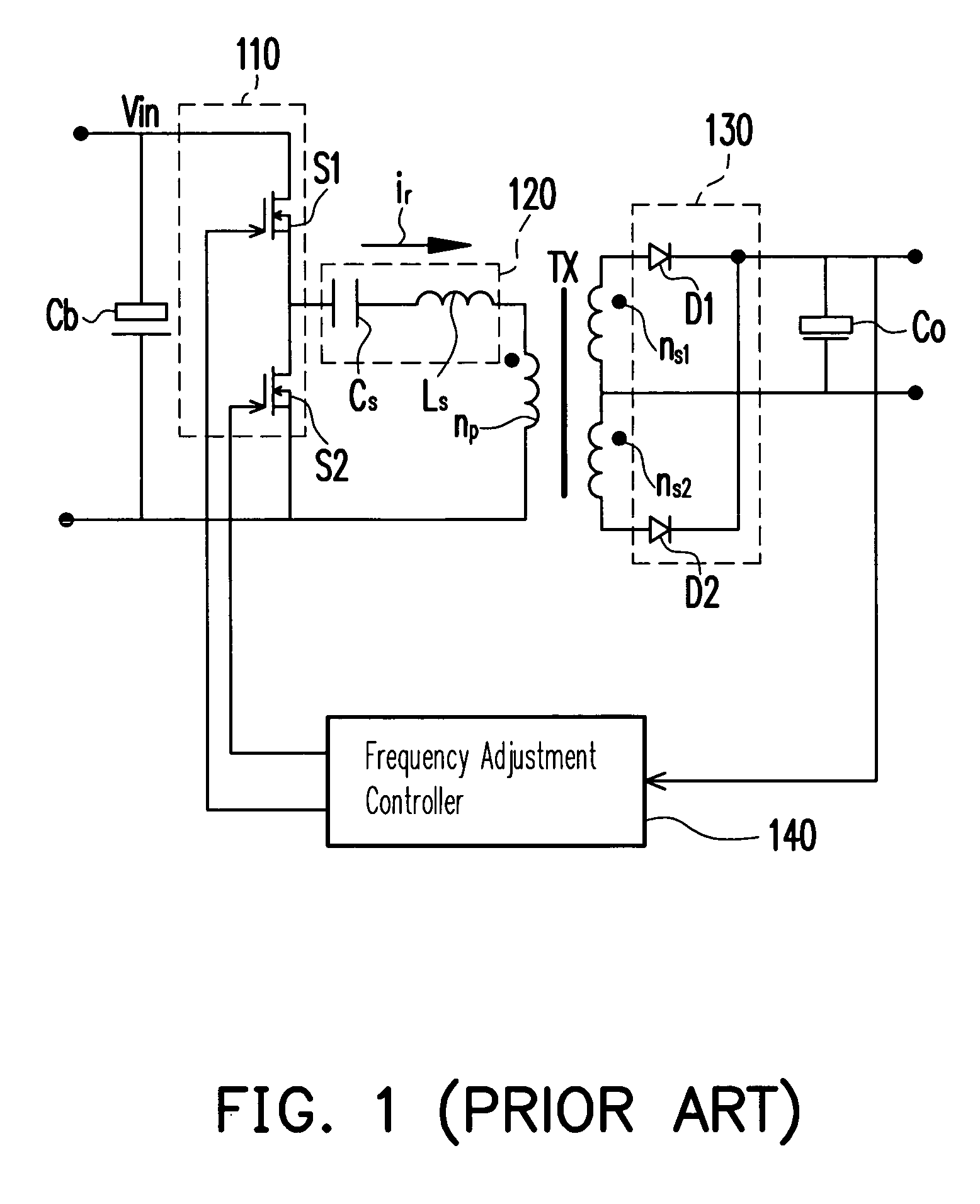
CROSS-REFERENCE TO RELATED APPLICATION[0001]This application claims the priority benefit of Taiwan application serial no. 94104986, filed on Feb. 21, 2005. All disclosure of the Taiwan application is incorporated herein by reference.BACKGROUND OF THE INVENTION[0002]1. Field of Invention[0003]The present invention relates to an LLC series resonant converter and the driving method for the synchronous rectification power switches, and particularly to an LLC series resonant converter adopting a frequency adjustment controller to provide driving signals and the driving method of the synchronous rectification power switches thereof.[0004]2. Description of Related Art[0005]FIG. 1 is a prior art circuit configuration of a widely used LLC series resonant converter (SRC) having a half-bridge structure. Here, LLC represents a circuit composed by two inductors and a capacitor. It includes a half-bridge circuit (110) formed by a pair of power switches S1 and S2 for driving a resonant network (12...

Claims


Application Information

Patent Timeline
Patent Type & Authority Patents(United States)
IPC IPC(8): H02M3/315
CPCH02M3/33592H02M3/3376Y02B70/1475Y02B70/1433Y02B70/10Y02P80/10
Inventor SUN, CHAOQUNGAN, HONGJIANYING, JIANPING
Owner DELTA ELECTRONICS INC
Learn More