
Dynamically adaptable electronics cooling fan

a cooling fan and dynamic technology, applied in the direction of wind motors with parallel air flow, emergency protective arrangements for automatic disconnection, etc., can solve the problems of less effective heat transfer from equipment to cooling airflow, significant heat generation of electronic equipment contained within the enclosure, and thermal damage to electronic equipmen

Active Publication Date: 2007-02-27
HEWLETT-PACKARD ENTERPRISE DEV LP
View PDF32 Cites 43 Cited by
  • Summary
  • Abstract
  • Description
  • Claims
  • Application Information

AI Technical Summary

Benefits of technology

The patent describes a way to detect when a cooling fan is failing and prevent air from flowing through it. This is done by rotating an impeller and expanding it in response to the fan failure, blocking the airflow. The technical effect is to improve the efficiency and reliability of cooling systems.

Problems solved by technology

Electronic equipment contained within the enclosure generates a significant amount of heat.
Thermal damage may occur to the electronic equipment unless the heat is removed.
If airflow patterns allow re-usage of air that is previously heated by electronic equipment component to attempt to cool electronic equipment, less effective heat transfer from the equipment to the cooling airflow can result.
In some circumstances insufficient heat transfer can take place and the equipment may overheat and potentially sustain thermal damage.
One re-circulation scenario occurs when a fan fails and hot air exhausted from other vents in the system may re-circulate back to the vicinity of the failed fan, greatly impacting thermal management for device.

Method used


Image

  • Dynamically adaptable electronics cooling fan
  • Dynamically adaptable electronics cooling fan
  • Dynamically adaptable electronics cooling fan

Examples


Embodiment Construction

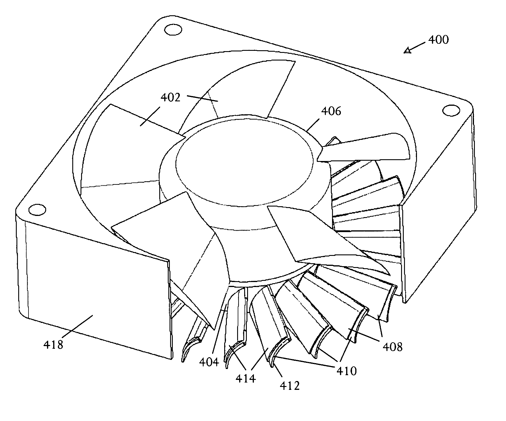
[0011]An electronics cooling fan dynamically responds to a failure condition by expanding structural fan members, blocking airflow and reducing or preventing recirculation of heated air.

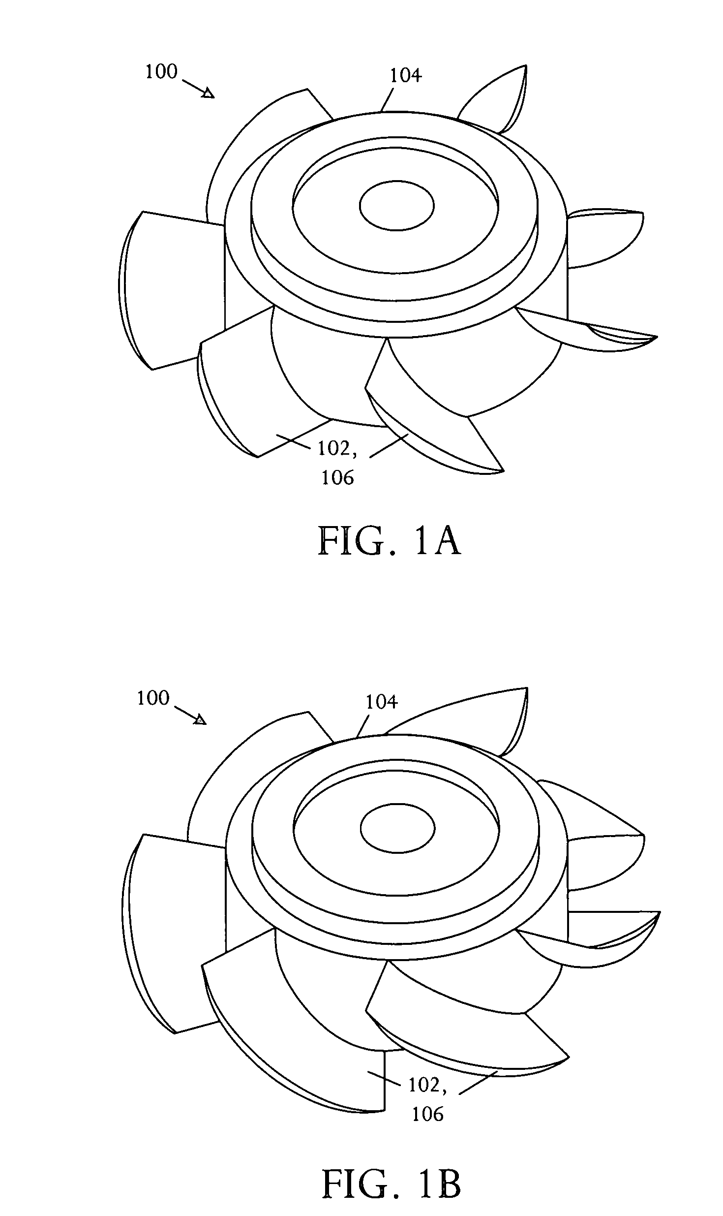
[0012]Referring to FIGS. 1A and 1B, perspective pictorial diagrams illustrate an embodiment of an electronics cooling fan 100 adapted to control air flow by selectively varying the thickness of structures within the air flow pathway. The electronics cooling fan 100 is arranged in a configuration adapted for rotational motion which generates an axial airflow pathway. The electronics cooling fan 100 comprises a member 102 arranged within the axial airflow pathway that is adapted to spatially expand when the rotational motion slows or terminates.

[0013]The electronics cooling fan 100 is configured to prevent airflow recirculation in a system when a fan fails. Various other techniques can be used to prevent or reduce airflow recirculation. For example, flexible air flow blockers can be added to the fans s...


PUM


Abstract

In an electronic system, a method for operating a cooling fan comprises rotating an impeller about a rotational axis and detecting fan failure. The impeller is spatially expanded in response to the detected fan failure whereby airflow through the failed fan is blocked.

Description

BACKGROUND OF THE INVENTION[0001]Electronic systems and equipment such as computer systems, network interfaces, storage systems, and telecommunications equipment are commonly enclosed within a chassis, cabinet or housing for support, physical security, and efficient usage of space. Electronic equipment contained within the enclosure generates a significant amount of heat. Thermal damage may occur to the electronic equipment unless the heat is removed.[0002]Re-circulation of heated air can impact performance of electronic equipment. If airflow patterns allow re-usage of air that is previously heated by electronic equipment component to attempt to cool electronic equipment, less effective heat transfer from the equipment to the cooling airflow can result. In some circumstances insufficient heat transfer can take place and the equipment may overheat and potentially sustain thermal damage.[0003]One re-circulation scenario occurs when a fan fails and hot air exhausted from other vents in...

Claims


Application Information

Patent Timeline
Patent Type & Authority Patents(United States)
IPC IPC(8): H05K7/20
CPCF04D29/388F04D29/382F04D25/0613F04D29/38F04D29/524F04D29/545F04D29/563
Inventor ESPINOZA-IBARRA, RICARDOSIMON, GLENNMALONE, CHRISTOPHER GREGORY
Owner HEWLETT-PACKARD ENTERPRISE DEV LP
Learn More