
Dosing device comprising a medium reservoir and corresponding pump device

Inactive Publication Date: 2007-02-27
APTAR RADOLFZELL
View PDF17 Cites 41 Cited by
  • Summary
  • Abstract
  • Description
  • Claims
  • Application Information

AI Technical Summary

Benefits of technology

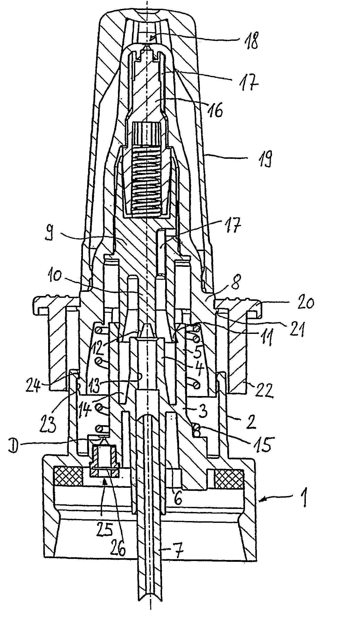
[0005]According to a development of the invention, on both sides the slide valve can be transferred into an open position over and beyond the dosing stroke, which makes it possible to bring about a particularly precise dosing. In addition, through the bilateral transferability of the slide valve into its open position a priming of the dosing device is made possible. Thus, when the dosing device is first put into operation the air volume in the pump chamber can be displaced, particularly into the medium reservoir. In the direction of the medium reservoir, i.e. away from the pump chamber, the slide valve passes into the open over and beyond the dosing stroke, i.e. into its open position facing the medium reservoir.
[0006]According to a further development of the invention the dosing stroke is formed by a housing-side dosing channel matched to the slide valve contour and which is bounded both towards the pump chamber and also the medium reservoir by in each case a cross-sectional widening. Preferably the dosing channel is formed on a detachably positioned component. Thus, as a function of the necessary dosing volume it is possible to use a suitable component with a dosing channel of differing length. The dosing channel length defines the dosing stroke and therefore also the dosing volume of the dosing device. By simply replacing the component the dosing device is made suitable for different uses. As soon as the slide valve has reached the particular cross-sectional widening, it opens, so that in both stroke directions the slide valve can be transferred into an open position.
[0007]According to a further development of the invention the pump chamber has at least one housing-side reception space, with which is associated a displacement body movable together with the slide valve and whose shape is matched to the cross-section of the reception space in such a way that the displacement body, on introduction into the reception space, almost completely fills the latter. This makes it possible to keep the clearance volume of the pump chamber of the dosing device extremely small, which further improves the dosing precision.
[0008]In a further development of the invention a pump spring arrangement used as a return stroke drive is positioned outside the flow paths of the medium to be dispensed and in particular outside the pump chamber. Therefore the pump spring arrangement cannot be attacked by the ingredients of the particular medium to be dispensed. Through the pump spring arrangement positioned outside the flow paths of the medium it is also ensured that there is no contamination of the medium by the pump spring arrangement and in particular by the corrosion thereof.
[0005]According to a development of the invention, on both sides the slide valve can be transferred into an open position over and beyond the dosing stroke, which makes it possible to bring about a particularly precise dosing. In addition, through the bilateral transferability of the slide valve into its open position a priming of the dosing device is made possible. Thus, when the dosing device is first put into operation the air volume in the pump chamber can be displaced, particularly into the medium reservoir. In the direction of the medium reservoir, i.e. away from the pump chamber, the slide valve passes into the open over and beyond the dosing stroke, i.e. into its open position facing the medium reservoir.
[0010]Improved use possibilities are created for the pumping device in that it is designed as a subassembly manufactured separately from the dosing device and detachably connectable to the latter. This makes it possible to construct the pumping device in a unitary manner and introduce it into different dosing devices.

Problems solved by technology

Therefore the pump spring arrangement cannot be attacked by the ingredients of the particular medium to be dispensed.
Thus, the return stroke spring arrangement cannot be attacked by ingredients of the medium.

Method used


Image

  • Dosing device comprising a medium reservoir and corresponding pump device
  • Dosing device comprising a medium reservoir and corresponding pump device
  • Dosing device comprising a medium reservoir and corresponding pump device

Examples


Embodiment Construction

[0018]A dosing device according to FIG. 1 has a cover 1, which can be locked onto a medium reservoir, preferably the form of a bottle-like or can-like container. For this purpose the cover 1 is cup-shaped and has on its inner circumference a not further designated annular shoulder, which can be locked onto a corresponding annular flange in a neck area of the medium reservoir. In an upper area of the cover 1 is provided a not designated, circumferential, elastic seal, which is compressed on locking the cover 1 on the medium reservoir neck and consequently ensures a tight sealing of the medium reservoir. A cup-like reception part 2 is integrally shaped onto the cover 1 and projects upwards counter to the not shown medium reservoir coaxial to a centre line axis of the cover 1. The reception part 2 forms an outer, jacket-like casing part for a subsequently further described pumping device, which is part of the dosing device of FIG. 1. A fixed pump casing part 3 is also provided integral...


PUM


Abstract

The invention relates to a dosing device that comprises a medium reservoir (S) and a pump device for dosing and dispensing a medium stored in said medium reservoir. The pump device is associated with a pump chamber, and with at least one inlet and one outlet valve. According to the invention, the inlet valve is configured as a sliding valve (10, 12) which, in its closed position, can be displaced by a dosing stroke that defines a dosing volume for the pump chamber (17). The invention further relates to the use of said dosing device for dispensing pharmaceutical active substances, especially for nasal administration.

Description

FIELD OF THE INVENTION[0001]The invention relates to a dosing device with a medium reservoir, as well as with a pumping device for dosing and dispensing a medium stored in the medium reservoir, a pump chamber, at least one inlet valve and at least one outlet valve being associated with the pumping device, as well as a pumping device for such a dosing device.BACKGROUND OF THE INVENTION[0002]DE 33 15 334 A1 discloses a dosing device provided with a pumping device and which is equipped with a medium reservoir for storing in particular liquid, pasty or creamy media. In addition to an inlet valve, an outlet valve and an additional outlet valve in the vicinity of an outlet opening are associated with the pump chamber, the additional outlet valve being opened by means of a stepped plunger or piston through a liquid pressure which has built up within the pumping device. For this purpose a valve body is provided and is urged into the closing direction by a spring web arrangement.[0003]The pr...

Claims


Application Information

Patent Timeline
IPC IPC(8): B05B9/04B05B11/00
CPCB05B11/0016B05B11/0021B05B11/0037B05B11/0043B05B11/307B05B11/3052B05B11/3059B05B11/3061B05B11/3016B05B11/0044B05B11/00444B05B11/0038B05B11/1016B05B11/026B05B11/1063B05B11/1059B05B11/107B05B11/1052
Inventor MBONYUMUHIRE, PIERRE
Owner APTAR RADOLFZELL
Learn More