Variable-magnification optical system and image taking apparatus
- Summary
- Abstract
- Description
- Claims
- Application Information
AI Technical Summary
Benefits of technology
Problems solved by technology
Method used
Image
Examples
first embodiment
[0048]An embodiment of the present invention will be described below with reference to the drawings.
1. Digital Still Camera
[0049]FIG. 7 is a block diagram showing the internal configuration of a digital still camera (DSC) 29 as an example of an image-taking apparatus according to the present invention.
[0050]As shown in FIG. 7, the DSC 29 includes a variable-magnification optical system OS, a flash FL, an optical system driving section 13, an image sensor SR, a signal processing section 14, a display section 15, a recording section 16, a recording medium 17, an operation section 18, and a control section 19.
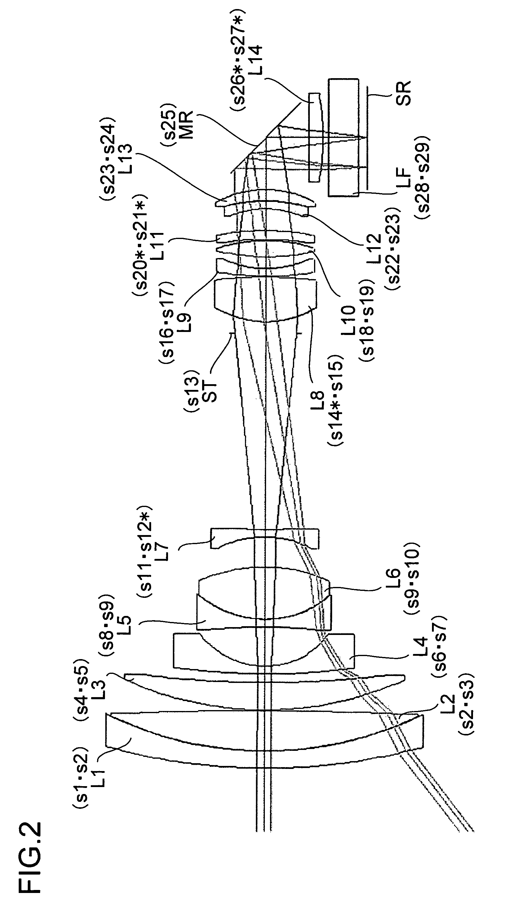
[0051]The variable-magnification optical system OS directs the light from the shooting target (subject, object) to the image sensor SR, and meanwhile images the light on the photosensitive surface (image surface) of the image sensor SR. Thus, the variable-magnification optical system OS may also be called an imaging optical system or an image-taking optical system. The variable-ma...
second embodiment
[0187]Another embodiment of the present invention will be described below with reference to the drawings. Such members as serve the same purposes as their counterparts in the first embodiment are identified with common reference numerals and symbols, and no explanations thereof will be repeated.
[0188]In the variable-magnification optical system OS (Example 1) of the first embodiment, the reflective mirror MR is disposed to the image side of the fourth lens group GR4. This, however, is not meant to limit the position of the reflective mirror MR in any way. To substantiate that, another (Example 2) example of the variable-magnification optical system OS will now be described with reference to FIGS. 8 and 9. In FIGS. 8 and 9, the same conventions as those used in FIGS. 1 and 2 are used.
1. Variable-Magnification Optical System of Example 2
[0189]The variable-magnification optical system OS of Example 2 shown in FIGS. 8 and 9 includes, from the shooting target (object) side, a first lens ...
PUM
 Abstract
Description
Claims
Application Information
 - R&D
- Intellectual Property
- Life Sciences
- Materials
- Tech Scout
- Unparalleled Data Quality
- Higher Quality Content
- 60% Fewer Hallucinations
Browse by: Latest US Patents, China's latest patents, Technical Efficacy Thesaurus, Application Domain, Technology Topic, Popular Technical Reports.
© 2025 PatSnap. All rights reserved.Legal|Privacy policy|Modern Slavery Act Transparency Statement|Sitemap|About US| Contact US: help@patsnap.com


