
Control system for vehicle having an engine capable of performing and stopping combustion in each cylinder

a control system and engine technology, applied in the direction of electric control, gearing, machines/engines, etc., can solve the problems of difference in engine output characteristic between cylinder groups, difference in engine output torque characteristic, etc., and achieve the effect of preventing improper determination

Active Publication Date: 2007-02-20
HONDA MOTOR CO LTD
View PDF9 Cites 55 Cited by
  • Summary
  • Abstract
  • Description
  • Claims
  • Application Information

AI Technical Summary

Benefits of technology

The present invention relates to a control system for vehicles with engines that have a plurality of cylinders that can switch between an all-cylinder operating condition and a partial-cylinder operating condition. The control system includes an engine switch control means for switching between the two operating conditions, a failure determining means for determining the failure of the lockup clutch and the lockup clutch control device, and a failure determination suspending means for suspending the failure determination during the switching of the engine operating condition. The technical effect of the invention is to prevent improper determination of the failure of the lockup clutch and the lockup clutch control device during the switching of the engine operating condition.

Problems solved by technology

In such an engine, there is a difference in engine output torque characteristic between an all-cylinder operating condition and a partial-cylinder operating condition due to the difference in number of cylinders, and there is also a difference in engine output characteristic between the cylinder groups due to a minute difference in machining error or assembly error.

Method used


Image

  • Control system for vehicle having an engine capable of performing and stopping combustion in each cylinder
  • Control system for vehicle having an engine capable of performing and stopping combustion in each cylinder
  • Control system for vehicle having an engine capable of performing and stopping combustion in each cylinder

Examples


Embodiment Construction

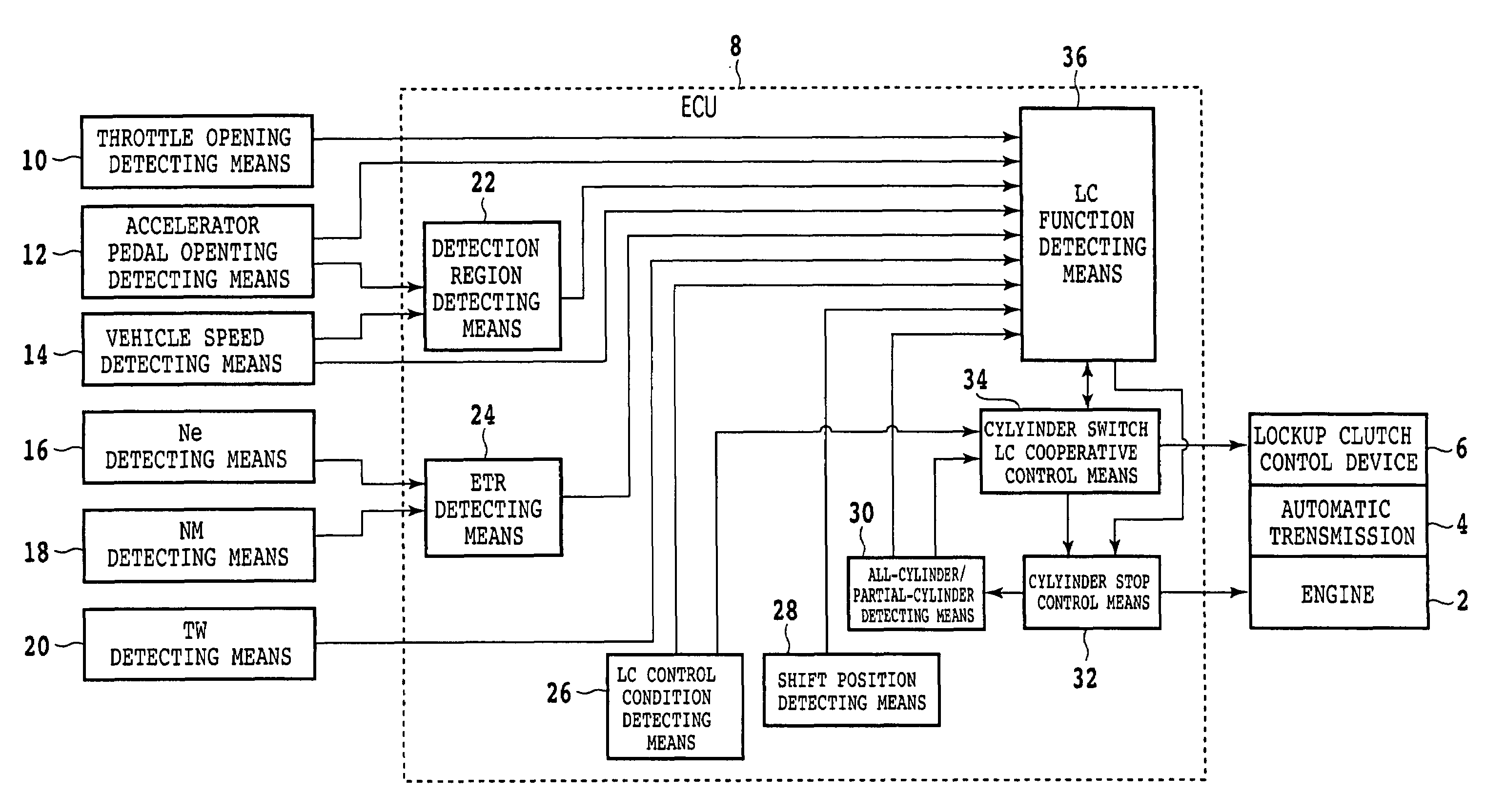
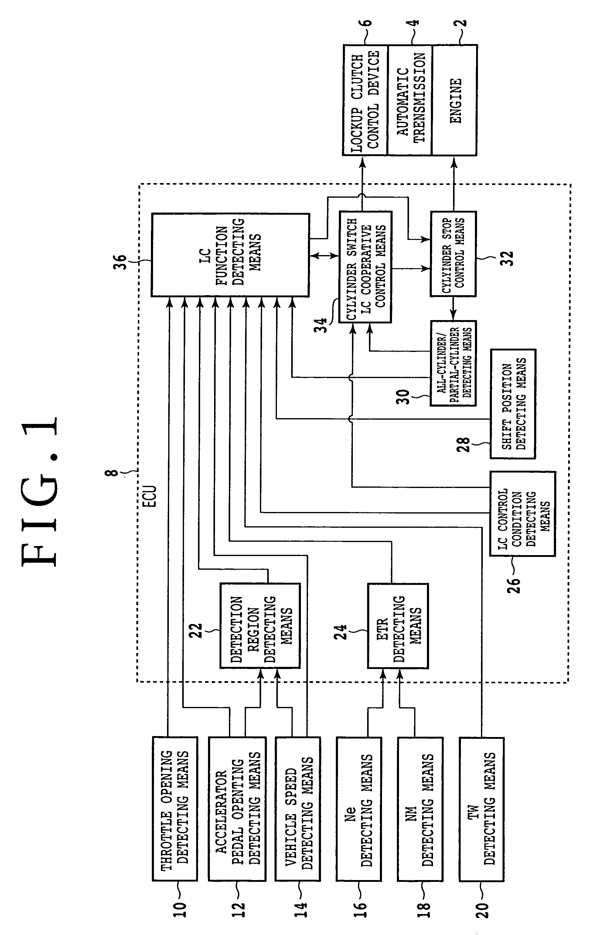
[0033]Referring to FIG. 1, there is shown a block diagram of a control system for a vehicle according to a preferred embodiment of the present invention. An automatic transmission 4 is connected to the crankshaft of an engine 2. The automatic transmission 4 has a torque converter with a lockup clutch. The lockup clutch is controlled by a lockup clutch control device 6. The engine 2 is an engine capable of performing and stopping combustion in each cylinder group. In other words, the engine 2 is an engine configured so that the cylinders of the engine are divided into a plurality of groups each consisting of a predetermined number of cylinders, wherein combustion stop control or combustion condition control by ignition timing or fuel injection amount is performed in each cylinder group. One example of such an engine is a V-type six-cylinder engine in which the above control is performed in each bank.

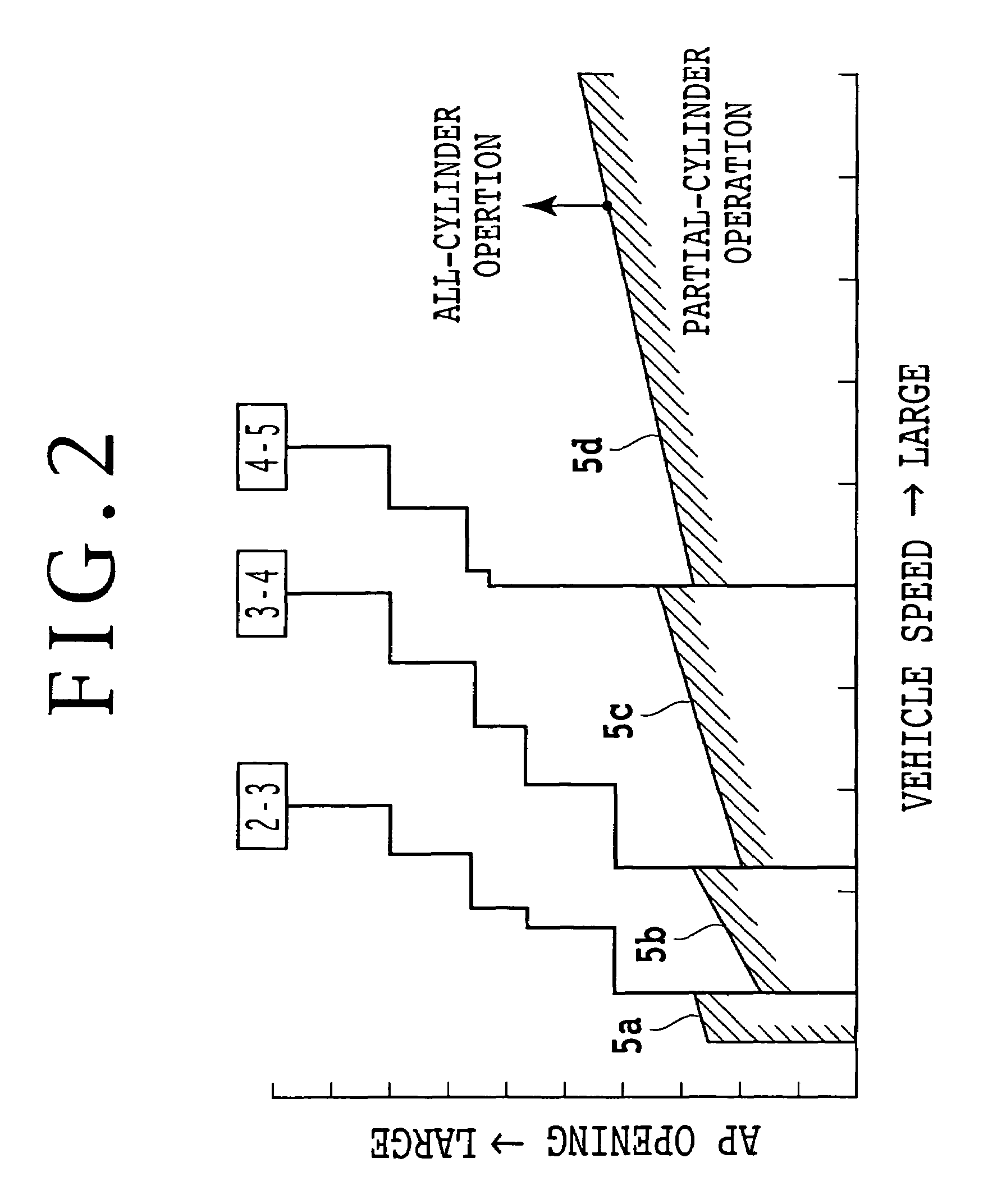
[0034]Referring to FIG. 2, there is shown an operating condition of the engine 2 acco...


PUM


Abstract

A control system for a vehicle includes an engine switch control unit for switching the operating condition of the engine between the all-cylinder operating condition and the partial-cylinder operating condition, a failure determining unit for determining the failure of the lockup clutch control device, and a coupling capacity change inhibiting unit for inhibiting a change in coupling capacity of the lockup clutch accompanied by the switch control of the operating condition of the engine by the engine switch control unit during the failure determination by the failure determining unit.

Description

BACKGROUND OF THE INVENTION[0001]1. Field of the Invention[0002]The present invention relates to a control system for detection of the failure of a lockup clutch in a vehicle having an engine capable of performing and stopping combustion in each cylinder group.[0003]2. Description of the Related Art[0004]A lockup clutch in an automatic transmission is usually engaged at a predetermined shift position for the purposes of improvement in fuel economy or the like. A method of controlling the slip amount of the lockup clutch according to an operating condition is generally adopted to absorb the shock due to complete engagement of the lockup clutch. For example, a target value for the slip amount of the lockup clutch in relation to the operating condition is preliminarily stored in a storage device according to a shift position, and the coupling capacity of the lockup clutch is controlled so that an actual slip amount becomes the target value.[0005]Further known is an engine capable of pe...

Claims


Application Information

Patent Timeline
Patent Type & Authority Patents(United States)
IPC IPC(8): B60W10/02B60W10/04B60W10/06B60W50/02F02D17/02F02D29/00F02D29/02F02D41/00F02D41/36F16H59/76F16H61/14F16H63/50
CPCB60W30/18F02D41/0087F16H61/12B60K2741/065F16H2061/1208F16H2061/1276Y10T477/747Y10T477/679Y10T477/75Y10T477/79Y10T477/6418Y10T477/735Y10T477/6433Y10S477/906B60W10/04B60W10/11B60W30/1819
Inventor KUSHIYAMA, HIROYUKINISHIO, SHINICHIKATAKURA, TAKEHIRONAKAJIMA, KENJI
Owner HONDA MOTOR CO LTD
Learn More