
Disaster recovery for processing resources using configurable deployment platform

a deployment platform and disaster recovery technology, applied in the field of disaster recovery systems and virtualized processing systems, can solve problems such as insufficient attention to processor-side issues, failure to transfer computer operations to secondary sites, and complex modern multi-tier application topologies

Active Publication Date: 2007-02-13
EGENERA
View PDF8 Cites 95 Cited by
  • Summary
  • Abstract
  • Description
  • Claims
  • Application Information

AI Technical Summary

Problems solved by technology

If a disaster were to happen at the primary site, e.g., a hurricane, computer operations may fail-over to the secondary site.
As suggested by FIG. 4, modern multi-tiered application topologies may become very complicated.
Processor-side issues have not received adequate attention.
This is complicated and costly, as suggested by the complexity of the multi-tiered architecture.
If such a network is a primary site network, then the changes also need to be made to the secondary, or else the enterprise risks that its disaster recovery system will not work as expected.

Method used


Image

  • Disaster recovery for processing resources using configurable deployment platform
  • Disaster recovery for processing resources using configurable deployment platform
  • Disaster recovery for processing resources using configurable deployment platform

Examples


Embodiment Construction

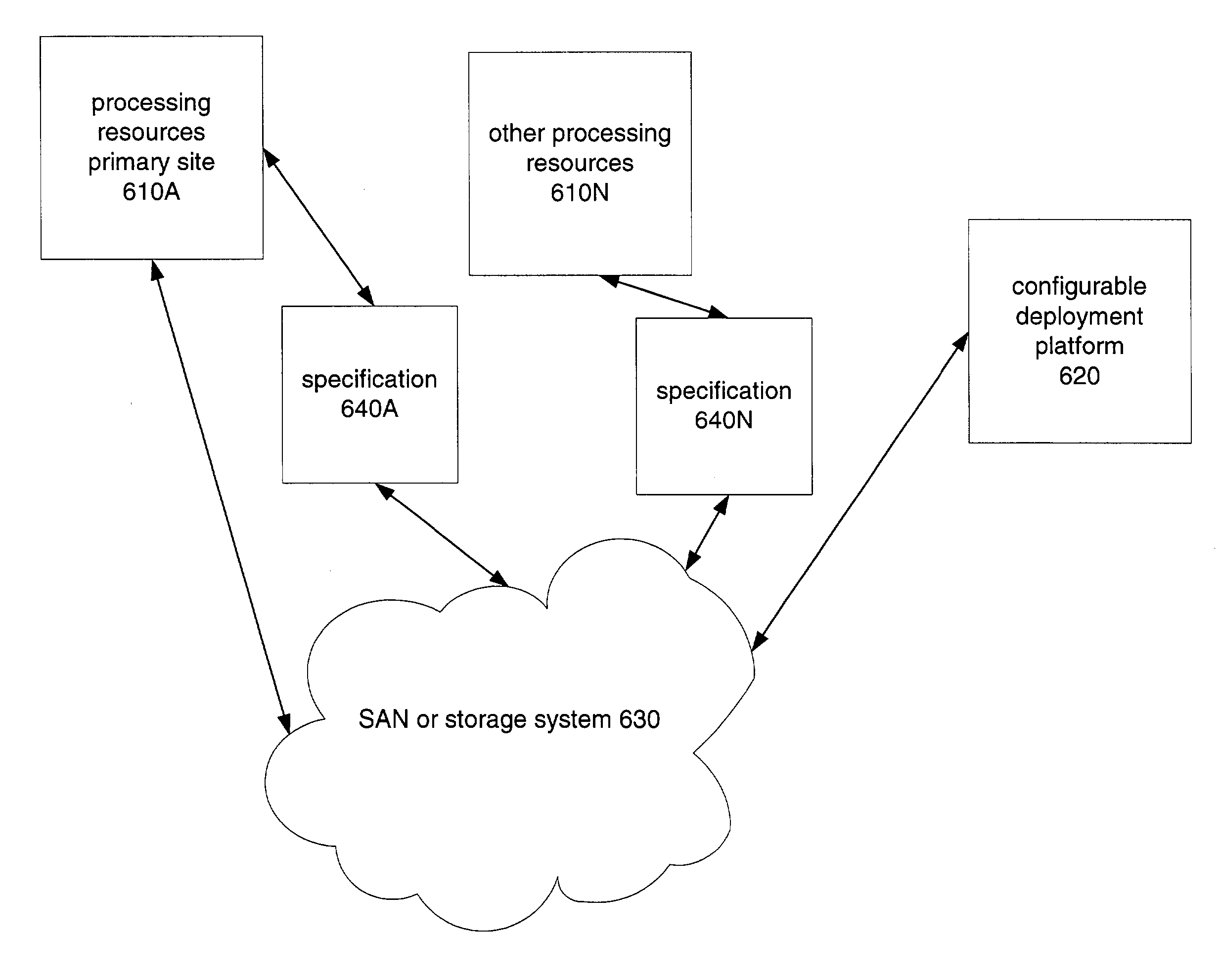
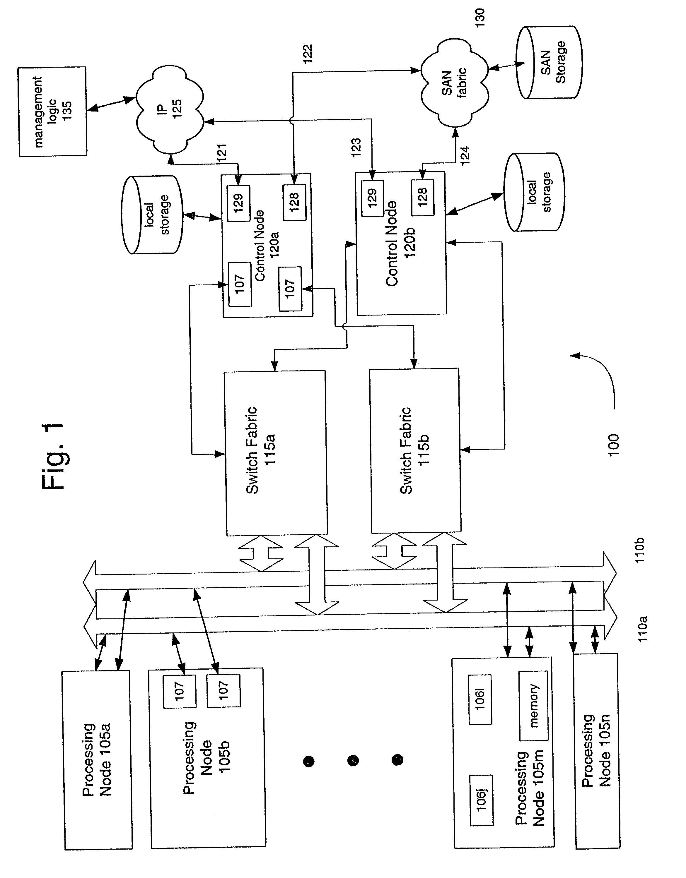
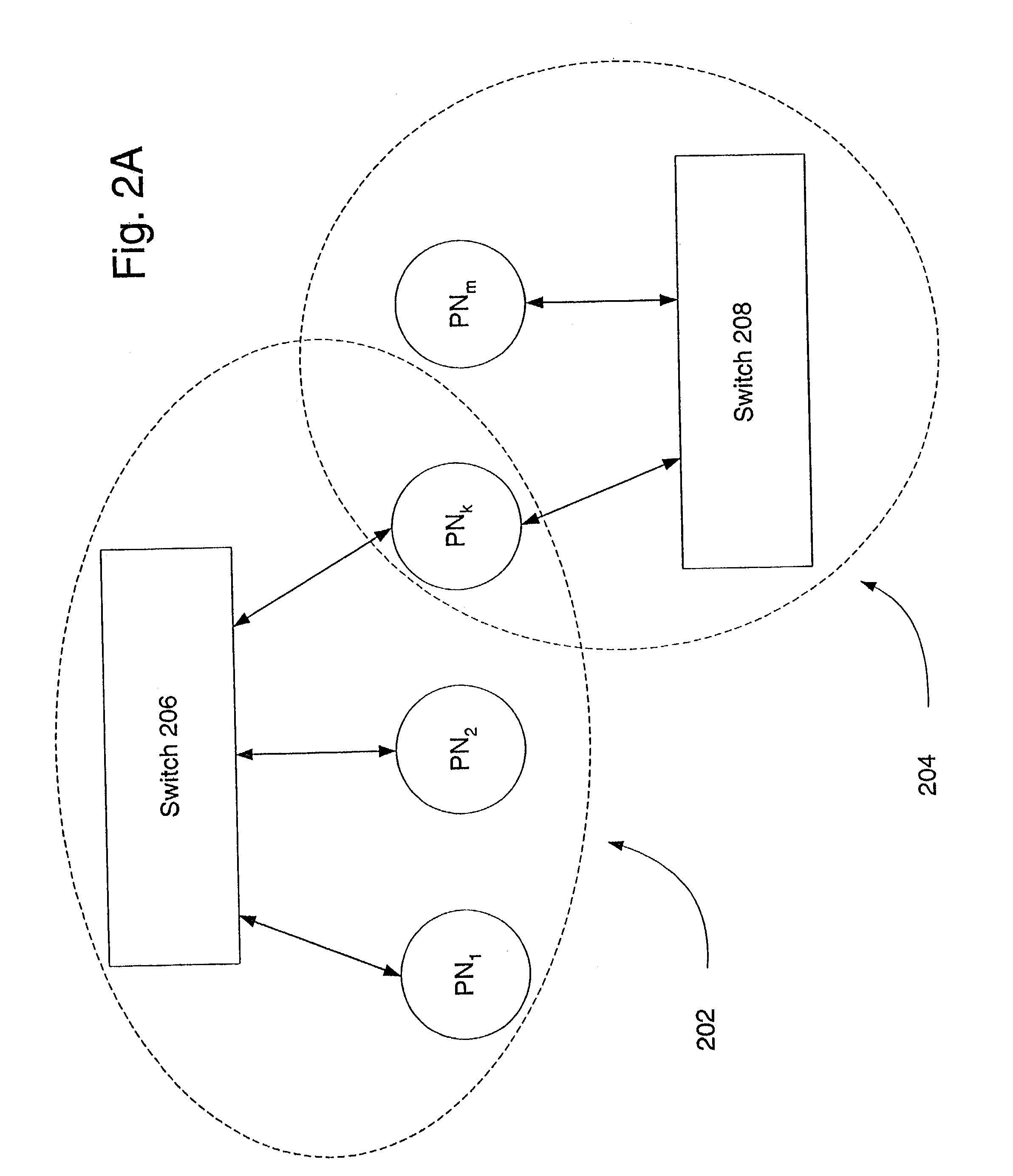
[0026]Preferred embodiments of the invention provide a system and method that enable the efficient failover of processing resources to a second, fail-over site. Processing resources and configuration at the primary site are characterized into a specification with a defined set of variables, and the specification is stored in a secure way. The set of information that characterizes the resources (i.e., the resource's “personality”) includes information such as the number of processing area networks (PANs) at the primary site, for each such PAN the number of nodes that should be allocated, the network connectivity among processors, storage mappings and the like (more below). The failover site uses a software-configurable platform that allows one or more independent processing networks to be deployed (or instantiated) in response to software commands. For example, certain embodiments may use the platform described in the U.S. patent applications identified above and incorporated by refe...


PUM


Abstract

A system and method for disaster recovery for processing resources using configurable deployment platform. A primary site has a configuration of processing resources. A specification of the configuration of processing resources of the primary site is generated. The specification is provided to a fail-over site that has a configurable processing platform capable of deploying processing area networks in response to software commands. Using the specification, software commands are generated to the configurable platform to deploy processing area network corresponding to the specifications.

Description

BACKGROUND[0001]1. Field of the Invention[0002]The present invention relates to computing systems for enterprises and, more specifically, to disaster recovery systems and techniques for reconfigurable, virtualized processing systems.[0003]2. Discussion of Related Art[0004]FIG. 3 depicts a conventional disaster recovery system. Storage facility 302 is located at a first location, and storage facility 304 is located at a second location, typically remote from the first location. Facility 302 may be considered a primary system and facility 304 may be considered as a secondary or fail-over site. Each facility has an identical copy of the data of interest, e.g., on their respective storage. Any desired updates of data at the primary are also sent to the secondary, e.g., via communication path 306. In this fashion, the primary and secondary facilities may maintain identical copies of data.[0005]If a disaster were to happen at the primary site, e.g., a hurricane, computer operations may fa...

Claims


Application Information

Patent Timeline
IPC IPC(8): G06F11/00G06F11/20H04L69/40
CPCG06F11/2023H04L29/06H04L69/40H04L67/1095H04L69/329G06F11/2028G06F11/2038H04L9/40
Inventor GREENSPAN, ALANGOODMAN-MACE, BORNEJOHNSON, MICHAELLIU, SIPINGKESWANI, CLAUDE
Owner EGENERA
Learn More