Vehicle surroundings display device and image providing system

a display device and vehicle environment technology, applied in television systems, instruments, printing, etc., can solve the problem of user not feeling unnaturalness, and achieve the effect of accurately recognizing the position of a neighboring object and eliminating unnaturalness the user may feel

Active Publication Date: 2007-02-13
PANASONIC CORP
View PDF15 Cites 30 Cited by
  • Summary
  • Abstract
  • Description
  • Claims
  • Application Information

AI Technical Summary

Benefits of technology

[0015]An object of the present invention is providing a vehicle surroundings display device capable of allowing the user to accurately recognize the position of a neighboring object that is important in driving operation and eliminating unnaturalness the user may feel due to failure of display of an image in an occlusion region.
[0016]Another object of the present invention is providing an image providing system capable of eliminating unnaturalness the user may feel for a region of a provided image in which image data from a camera is not available due to existence of an object.
[0021]According to the invention described above, when an obstacle in the surroundings of a vehicle is detected by the obstacle detection means, an image missing region failing to obtain image data from the camera due to existence of the obstacle and the like is detected by the image missing region detection means. The image processor fills at least part of the image missing region with substitute image data. In the resultant surroundings image generated by the image processor, unnaturalness of the image missing region corresponding to the “occlusion region” described above is reduced by the filling with substitute image data, and camera image data is used for the portion other than the image missing region corresponding to the “non-concealed region”. Therefore, the user does not feel unnaturalness for the surroundings image so much and can recognize the position of the obstacle in the surroundings of the vehicle accurately. Thus, safe driving operation is possible more reliably and comfortably than in the conventional case.
[0024]Preferably, the image processor places the border image on the surroundings image so as to align with the border position detected by the obstacle position detection means, presumes a region occupied by the obstacle in the surroundings image by aligning with the border position, and generates the substitute image data by pixel interpolation using pixel data of the border image for a portion of the presumed obstacle region other than the border image. Thus, the border image is placed in the accurate border position, and an image of the portion of the obstacle other than the border image is generated by pixel interpolation using pixel data of the border image. This enables generation of a surroundings image in which the border position of the obstacle on the user's vehicle side, important for the user, is accurate and for which the user does not feel unnatural.
[0025]Preferably, when the obstacle is an axisymmetric object, the image processor assumes a symmetry axis of the obstacle in the surroundings image, inverts the border image with respect to the symmetry axis to provide an inverted border image, and generates an image between the border image and the inverted border image in the obstacle region by the pixel interpolation using pixel data of the border image. This enables generation of a synthesized image of an occlusion region free of unnaturalness by use of axisymmetry of the object such as a vehicle.
[0034]According to the present invention, when an object is detected in the image-provided range, an image missing region failing to obtain image data from the camera due to existence of the object is detected by the image missing region detection means. The image processor fills at least part of the image missing region with substitute image data. In the resultant provided image generated by the image processor, unnaturalness of the image missing region is reduced by the filling with substitute image data, and camera image data is used for the portion other than the image missing region. Therefore, the user does not feel unnaturalness for the provided image so much and can recognize the situation in the image-provided range accurately.

Problems solved by technology

As for the occlusion region, it is considered that an accurate image in an accurate position is not necessarily required, but display to a degree of accuracy that the user does not feel unnaturalness is sufficient.

Method used


Image

  • Vehicle surroundings display device and image providing system
  • Vehicle surroundings display device and image providing system
  • Vehicle surroundings display device and image providing system

Examples


embodiment 1

[0095]FIG. 1 conceptually shows a basic configuration of a vehicle surroundings display device of Embodiment 1 of the present invention. The vehicle surroundings display device of FIG. 1 includes, as a basic configuration: a camera 11 for taking images of the surroundings of a vehicle; an obstacle detection means 12 for detecting an obstacle in the surroundings of the vehicle; an obstacle position detection means 13 for detecting the position of the border of the obstacle on the vehicle side; and an image processor 14 receiving the images taken with the camera 11 (camera images) for generating an image showing the situation around the vehicle from the received camera images.

[0096]The camera 11 is typically mounted on the vehicle for taking images of the situation around the vehicle. Cameras placed somewhere in infrastructures such as roads, signals and buildings may also be used. Otherwise, images taken with cameras mounted on other vehicles around the user's vehicle, if any, may be...

embodiment 2

[0116]The vehicle surroundings display device of Embodiment 2 of the present invention has a basic configuration as shown in FIG. 1, as in Embodiment 1, that is, has the camera 11, the obstacle detection means 12, the obstacle position detection means 13 and the image processor 14 as main components.

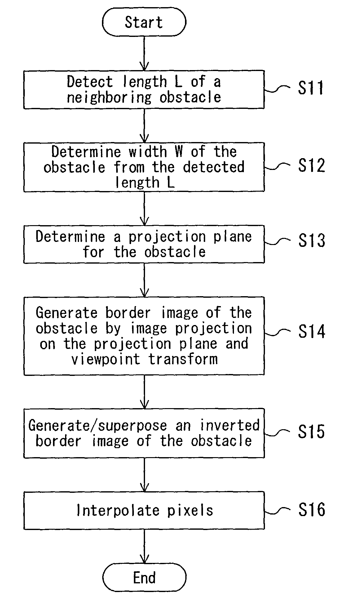
[0117]This embodiment is different from Embodiment 1 in the function of the image processor 14. In this embodiment, when an obstacle is detected by the obstacle detection means 12, the image processor 14 uses a border image including at least a border portion of the obstacle on the user's vehicle side detected by the obstacle position detection means 13 to generate substitute image data for filling an image missing region, and displays the substitute image data in an accurate position so that the user does not feel unnaturalness for the resultant image.

[0118]In many cases, obstacles in the surroundings of a vehicle are roughly axisymmetric as cars are. In the following example, the axisy...

embodiment 3

[0150]FIG. 23 shows a basic configuration of a vehicle surroundings display device of Embodiment 3 of the present invention. Referring to FIG. 23, the vehicle surroundings display device of this embodiment includes an obstacle image database 31 for storing image data of objects as potential obstacles, in addition to the camera 11, the obstacle detection means 12, the obstacle position detection means 13 and an image processor 14A.

[0151]The operation of the image processor 14A is different from the image processor 14 in Embodiments 1 and 2. That is, the image processor 14A determines the type of an obstacle detected by the obstacle detection means 12, reads image data for the determined type of obstacle from the obstacle image database 31, and places the read image data on a surroundings image to align with the border position detected by the obstacle position detection means 13 as substitute image data filling an image missing region of the surroundings image.

[0152]The determination...


PUM


Abstract

In the vehicle surroundings display device of the invention, an image processor generates an image showing the situation around a vehicle. When an obstacle is detected by an obstacle detection means, the image processor determines an image missing region using the position of the border of the obstacle on the vehicle side detected by an obstacle position detection means and fills the image missing region with substitute image data. This eliminates unnaturalness of a display image the user may feel and enables the user to accurately recognize the position of a neighboring obstacle that is important in driving operation.

Description

BACKGROUND OF THE INVENTION[0001]The present invention relates to a vehicle surroundings display device for displaying the surroundings of a vehicle as an image, and more particularly, relates to a technology enabling the user to recognize the surroundings of a vehicle easily and accurately for safer driving operation.[0002]In conventional general vehicle surroundings display devices, images of the surroundings of a vehicle are taken with one camera or several cameras, and the taken images are transformed so that the situation around the vehicle is shown by one image. For example, in Japanese Patent Publication No. 62-16073 (first prior art), a plurality of cameras are mounted on a car. Video outputs from the cameras are changed to coordinates in a plane coordinate system with the car positioned in the center, to be synthesized as one image so that the driver can recognize the situation around the car at a glance.[0003]In Japanese Laid-Open Patent Publication No. 7-223488 (second pr...

Claims


Application Information

Patent Timeline
IPC IPC(8): H04N7/18G01S11/12G01S17/931G03B29/00
CPCG01S11/12G01S17/936G01S17/931
Inventor SATONAKAGAWA, MASAMICHIOKAMOTO, SHUSAKUMORIMURA, ATSUSHIMATSUKAWA, YOSHIHIKONOBORI, KUNIO
Owner PANASONIC CORP
Why Eureka
Try Eureka