
Subsea production system

Active Publication Date: 2007-02-13
VETCO GRAY SCANDINAVIA
View PDF14 Cites 12 Cited by
  • Summary
  • Abstract
  • Description
  • Claims
  • Application Information

AI Technical Summary

Benefits of technology

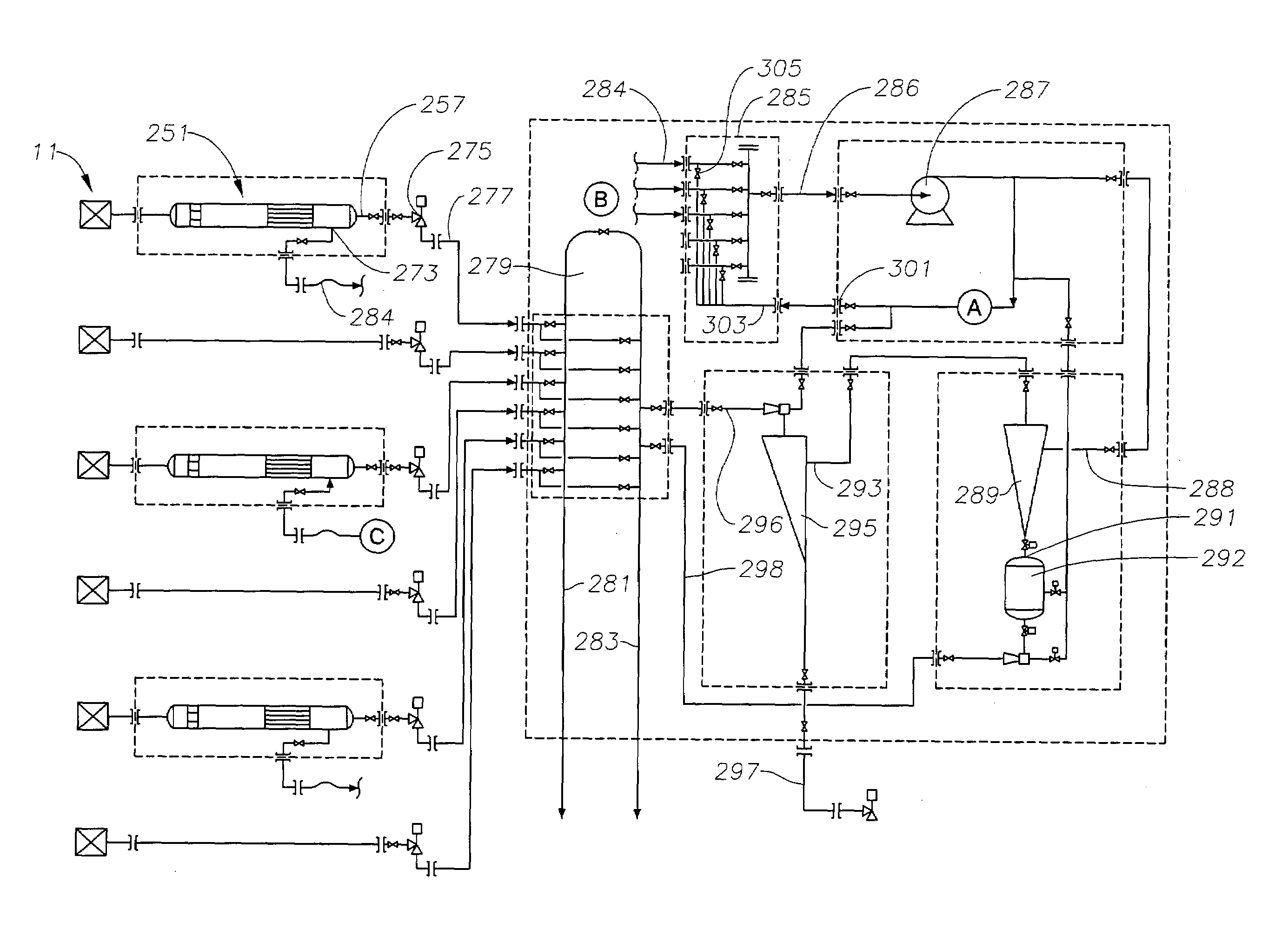
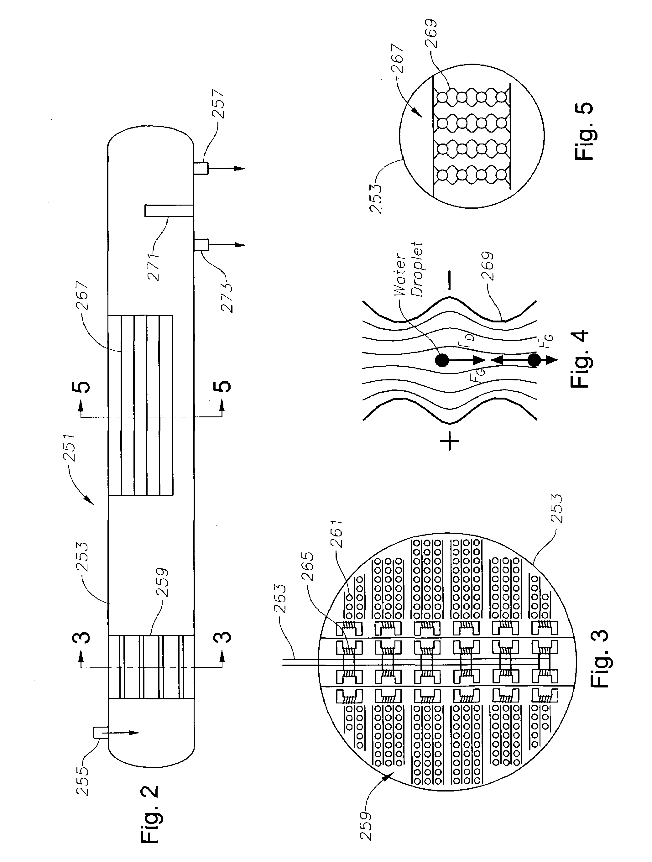
[0006]In this invention, a choke located downstream of the separator for limiting the flow rate of well fluid from the subsea well. The placement of the choke allows higher operating pressures in the separator, which facilitates separation. The separator has a cylindrical chamber, preferably with a length at least ten times its diameter. A coalescing unit having a plurality of tubes to which an electrical potential is applied is located in the chamber to cause water droplets in the well fluid flowing through the tubes to coalesce into larger droplets. Also, preferably a dielectrophoresis unit is located in the chamber downstream of the coalescent unit. The dielectrophoresis unit has a pair of undulating sheets spaced close to each other, the sheets being supplied with an electrical potential to force the water droplets in the well fluid into predetermined passage portions between the sheets to form high water content sections of liquid.

Problems solved by technology

In deep water installations, thousands of feet deep, the energy required to pump the water is extensive.
While vessels can be made stronger, generally this results in a larger size and weight.
Larger size and weight increase the difficulty of deploying the units.
Also, separators commonly require maintenance because of sand accumulation and mineral deposits on the components.
Once installed subsea, maintenance becomes difficult because of the sea depths.
Further, shutting down a separation system for maintenance would normally require shutting off well flow, which is expensive.

Method used


Image

  • Subsea production system
  • Subsea production system
  • Subsea production system

Examples


Embodiment Construction

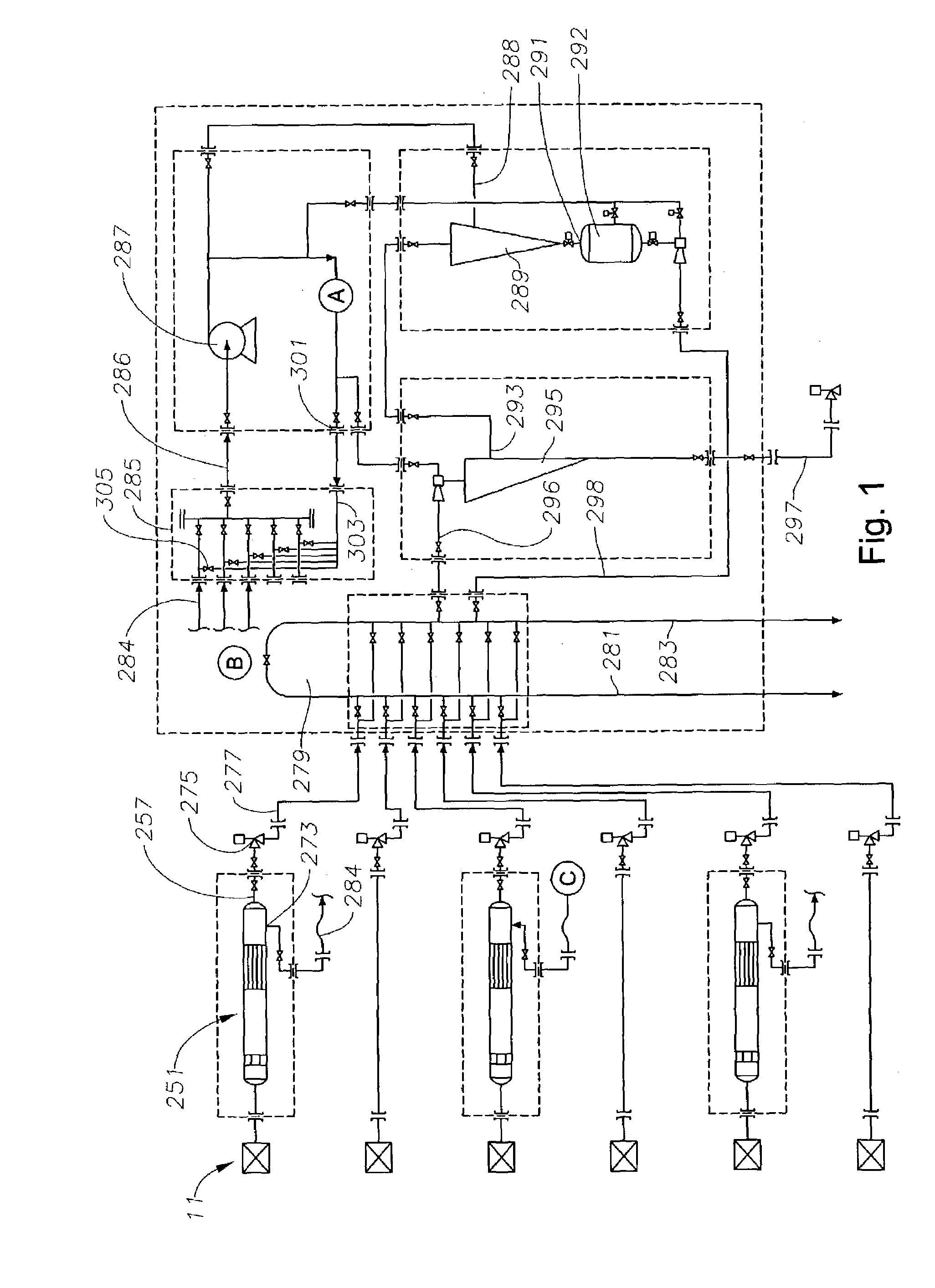
[0013]FIG. 1 illustrates schematically a subsea processing system for the various wells 11 within a field. The subsea processing systems separates water and sand. The system includes a plurality of separators 251. A single separator 251 may be utilized with each subsea well assembly 11, or more than one well 11 may feed into a separator 251. Separator 251, as shown in FIG. 2, comprises a horizontal vessel 253 that locates on the sea floor. Generally, greater water depths will require a higher wellhead pressure with corresponding lower actual gas volumes when separation takes place at the sea floor. Lower gas volumes are beneficial for oil / water separation because fewer gas bubbles will move vertically and disturb the horizontal flow pattern generated by the oil and water flowing through the separator vessel 253. The low gas percentage also allows more of the separator vessel to be utilized for oil / water separation.

[0014]In addition to the issue described above, higher pressure in it...


PUM

PropertyMeasurementUnit
Lengthaaaaaaaaaa
Pressureaaaaaaaaaa
Flow rateaaaaaaaaaa

Abstract

A subsea well fluid processing system has a separator for separating heavier and lighter components of well fluid flowing from a subsea well and directing the lighter components to flow to a surface processing facility. A choke is located downstream of the separator for limiting the flow rate of well fluid. The separator has a cylindrical chamber having a length at least ten times its diameter. A coalescing unit located in the chamber causes water droplets in the well fluid to coalesce into larger droplets. A dielectrophoresis unit having undulating sheets spaced close to each other is also located in the chamber. The sheets of the unit are supplied with an electrical potential to force the water droplets into predetermined passage portions to form high water content sections of liquid. Bypass valves allow backflushing of one of the separators while others continue to operate.

Description

[0001]This application claims the provisional application Ser. No. 60 / 356,108, filed Feb. 11, 2002 and provisional application Ser. No. 60 / 425,377, filed Nov. 12, 2002.FIELD OF THE INVENTION[0002]This invention relates in general to well fluid processing systems and in particular to a subsea system.BACKGROUND OF THE INVENTION[0003]Oil and gas wells typically produce a well fluid that requires separation to remove formation water from the flow stream. With subsea wells, the separation typically takes place on a production platform or vessel. This usually requires pumping the well fluid, including the formation water, to the surface production facility. In deep water installations, thousands of feet deep, the energy required to pump the water is extensive.[0004]Locating the separation unit subsea has been proposed and done on at least one occasion. The environment of a subsea separation unit and a surface unit differs because of the high hydrostatic forces imposed on the separation ve...

Claims


Application Information

Patent Timeline
IPC IPC(8): G01N27/447B03C5/02E21B34/04E21B43/00G01N27/453B01D17/00B01D17/02B01D17/032C02F1/40C02F1/48E21B33/038E21B43/12E21B43/36E21B43/40
CPCB01D17/00B01D17/0211E21B43/40E21B43/36E21B43/12E21B33/038C02F1/48B01D17/0208B01D17/0217B01D17/045B01D17/06B01D17/0214C02F2103/10C02F2103/06C02F2101/32C02F1/40B01D17/12E21B43/35
Inventor MICHAELSEN, JARLENILSEN, PAAL J.
Owner VETCO GRAY SCANDINAVIA
Learn More