Tangential stress reduction system in a loudspeaker suspension

a technology of tangential stress reduction and suspension element, which is applied in the direction of transducer diaphragm, loudspeaker diaphragm shape, instruments, etc., can solve the problems of limiting the performance of speakers, reducing the excursion of the diaphragm, and not being able to meet the needs of smaller speakers, so as to improve the performance of the speaker, minimize the stress on the suspension element, and increase the amount of excursion and linearity of the diaphra

Inactive Publication Date: 2007-02-13
HARMAN INT IND INC
View PDF16 Cites 14 Cited by
  • Summary
  • Abstract
  • Description
  • Claims
  • Application Information

AI Technical Summary

Benefits of technology

[0011]The invention provides designs for suspension elements that, in the case of the surround, increases the amount of excursion and linearity of the diaphragm and thereby improves the performance of the speaker. The design of the suspension elements minimizes the stress on the suspension elements by incorporating various geometric designs into the suspension elements that allow the suspension elements to stretch more easily. The design is incorporated in to the suspension elements without modifying the perimeter size of the elements, allowing for greater excursion of the diaphragm and movement of the voice coil in the same size speaker. In addition to improving the excursion, a significant reduction in the stiffness of the suspension elements is also achieved. This allows for greater bass reproduction in the same size speaker. Further, the modifications to the stiffness also allow for a greater range of operation with constant stiffness, which assists in reducing distortion by allowing the force vs. deflection characteristics to be tailored.

Problems solved by technology

Employing bigger suspension elements, is not, however, a viable solution in a smaller speaker design since the size of the diaphragm must be significantly reduced to accommodate a larger suspension.
When a small surround is utilized the excursion of the diaphragm is reduced, limiting the performance of the speakers.

Method used


Image

  • Tangential stress reduction system in a loudspeaker suspension
  • Tangential stress reduction system in a loudspeaker suspension
  • Tangential stress reduction system in a loudspeaker suspension

Examples


Embodiment Construction

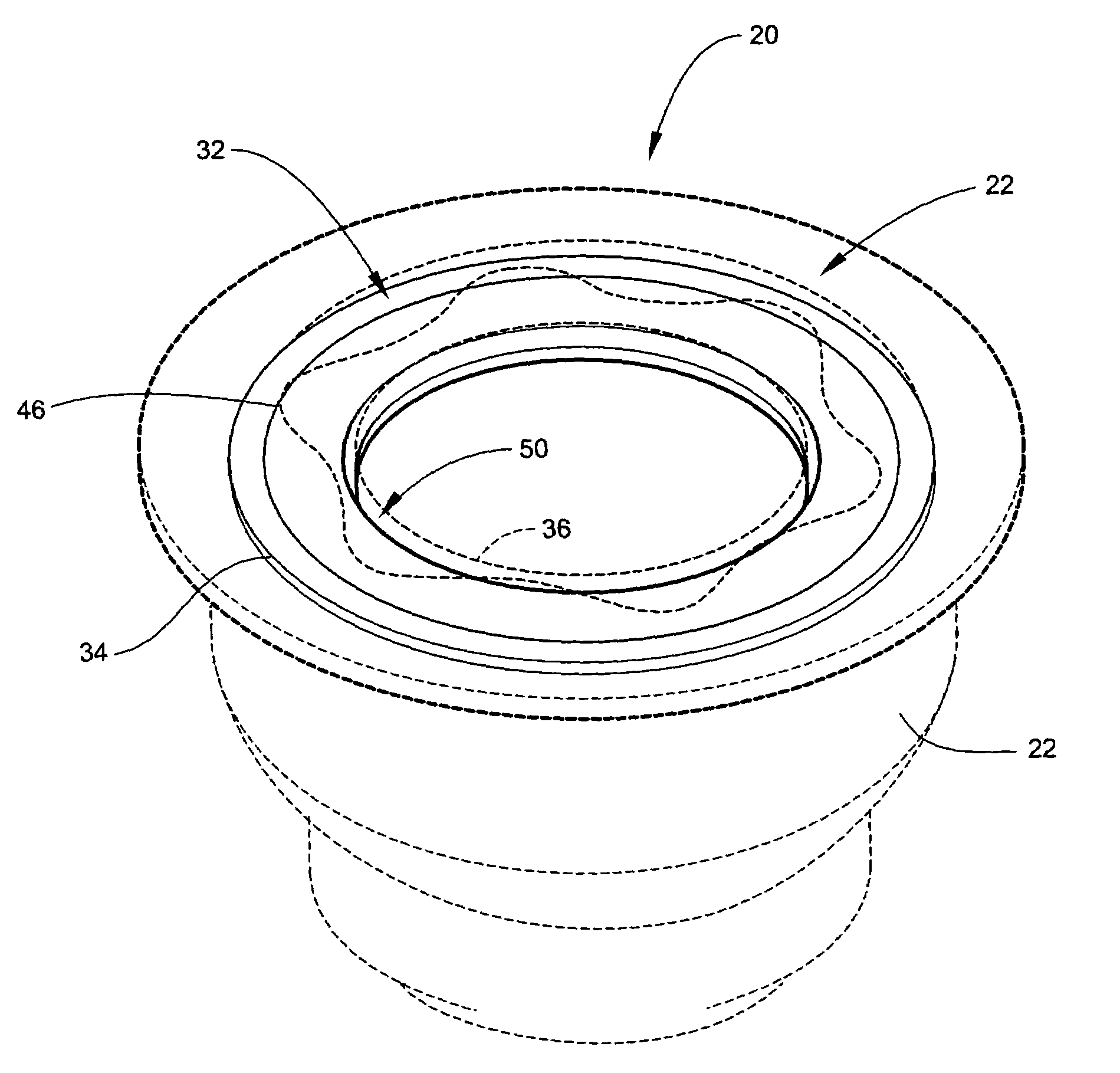
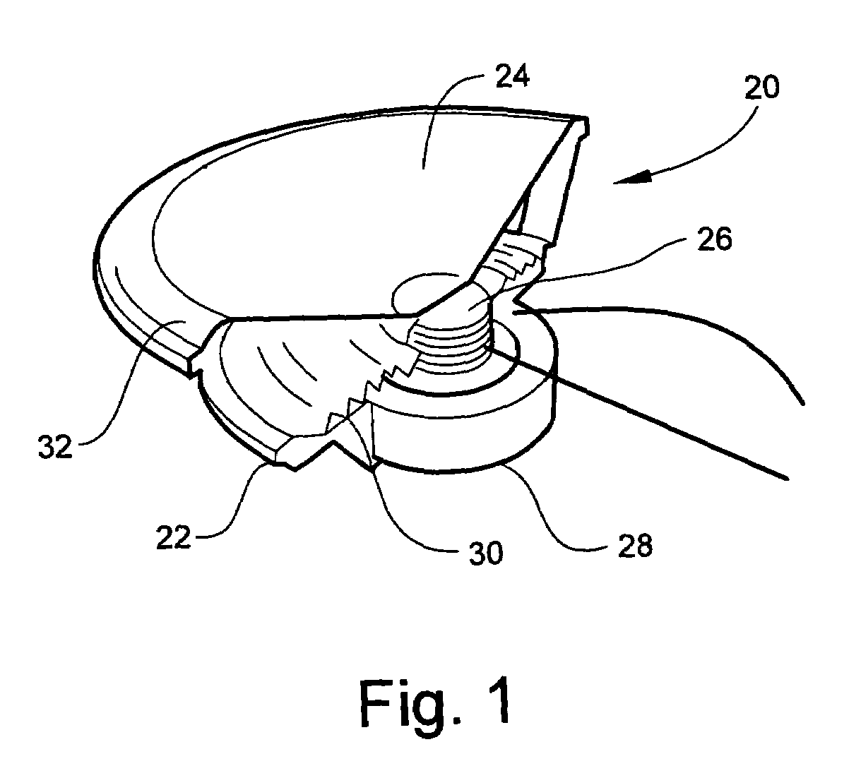
[0035]FIG. 1 is a cut away perspective view of a speaker 20, which illustrates the general construction of a traditional speaker 20. A speaker 20 generally includes, among other things, a frame 22, a diaphragm 24, a voice coil 26, a magnet 28, a spider 30 and a surround 32.

[0036]The voice coil 26 is attached to the underside of the diaphragm 24. The voice coil 26 and diaphragm 24 are attached to the frame 22 via a suspension system, which generally comprises two suspension elements, the spider 30 and the surround 32. The spider 30 is attached to both the frame 22 and the voice coil 26. The spider 30 is attached to the voice coil 26 in manner that holds the voice coil 28 in position, yet allows the voice coil 26 to freely move up and down. Similarly, the diaphragm 24 is attached to the frame 22 via a surround 32. Alternatively, the surround 32 may be attached to a cylinder (not shown) that is in turn attached to the diaphragm 24. In this regard, U.S. patent application Ser. No. 09 / 34...


PUM


Abstract

The invention is a suspension element having an outer edge and an inner edge. The suspension element, such as a spider or surround, varies in shape along at least a portion of the suspension element to help relieve both the radial and tangential stress placed on the suspension element when it is stretched. The shape employed in the suspension element allows the suspension element to stretch more easily, creating a higher performance speaker of the same size by increasing the diaphragm excursion and voice coil movement.

Description

RELATED APPLICATIONS[0001]This application is a continuation of U.S. application Ser. No. 10 / 113,627 filed on Mar. 27, 2002 now U.S. Pat. No. 6,851,513, which claims priority to U.S. provisional patent application Ser. No. 60 / 279,314, filed Mar. 27, 2001, both application of which are incorporated by reference is incorporated into this application in their entirety by reference.BACKGROUND OF THE INVENTION[0002]1. Field of the Invention[0003]This invention relates to the reduction of tangential and radial stress in a suspension element of a loudspeaker transducer. In this invention, the suspension element, such as a surround or spider, is designed to increase its ability to expand in both the radial and tangential directions.[0004]2. Related Art[0005]Sound reproduction devices such as loudspeakers are utilized in a broad range of applications in many distinct fields of technology, including both the consumer and industrial fields. Sound reproduction devices utilize a combination of m...

Claims


Application Information

Patent Timeline
Patent Type & Authority Patents(United States)
IPC IPC(8): H04R7/00G10K13/00H04R7/20
CPCG10K13/00H04R9/043H04R7/20H04R2307/207
Inventor STEAD, BRENDONWILLIAMSON, CLAYTONTRAINER, MARK
Owner HARMAN INT IND INC
Why Eureka
Try Eureka