
Flange sleeve, method for the production thereof and bending tool for producing flanges on a sleeve

Inactive Publication Date: 2007-02-13
FEDERAL MOGUL WIESBADEN
View PDF6 Cites 6 Cited by
  • Summary
  • Abstract
  • Description
  • Claims
  • Application Information

AI Technical Summary

Benefits of technology

[0014]It is therefore the object of the invention to provide a bush with closed or extensively closed butt joint which does not cost any more to produce than the conventional flanged bushes obtained by bending.
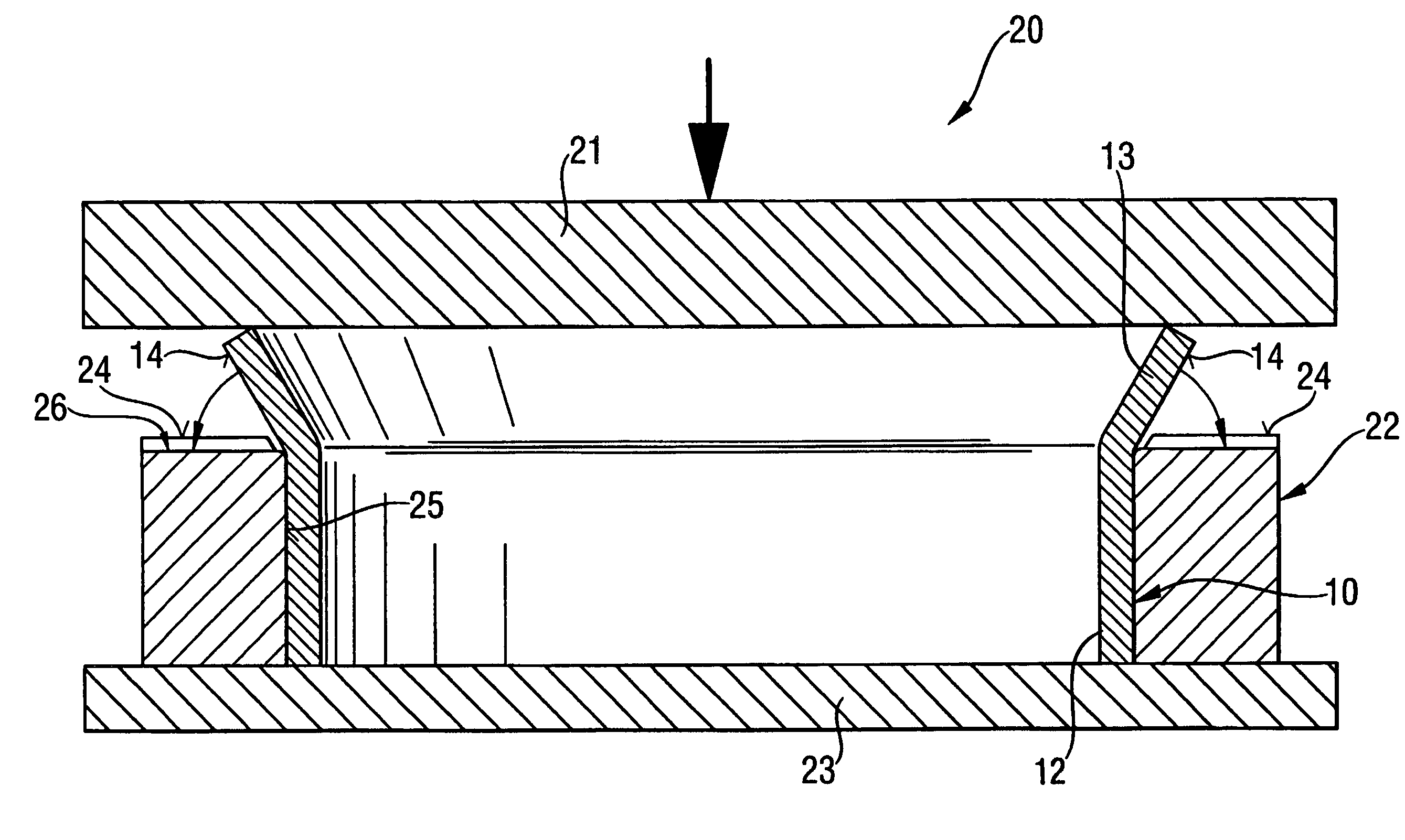
[0021]The recesses are preferably produced when bending the bush edge. Incorporation into the bending process has the advantage that no additional method step is necessary, such that the production costs do not increase relative to conventional flanged bushes. If the material-displacing recesses are formed in the flange during bending, the butt joint cannot open in the first place.
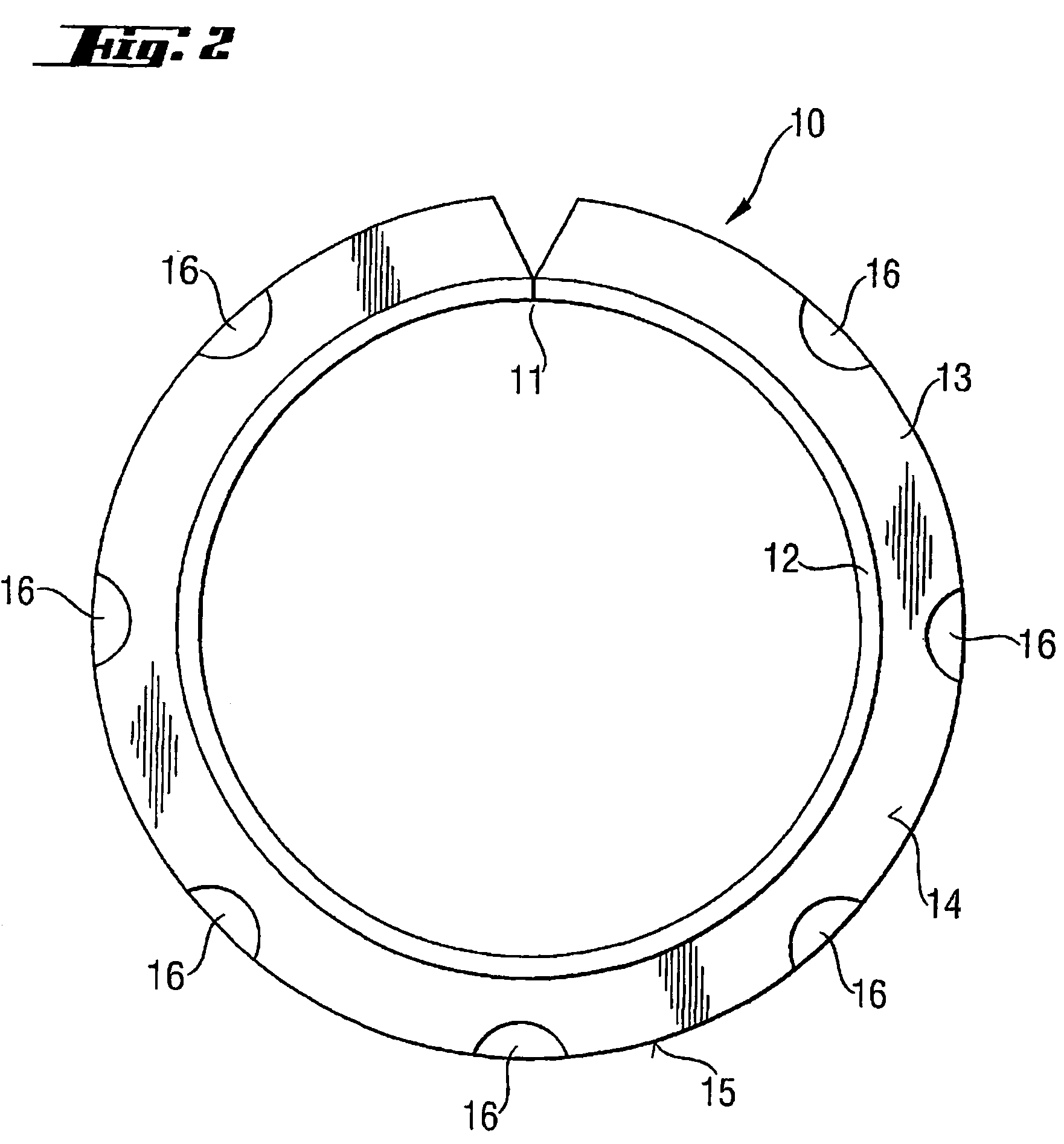
[0024]The recesses preferably take the form of impressions, and are preferably located in the inner and / or outer surface of the flange. In a further preferred embodiment, the recesses extend as far as into the outer edge of the flange. It has been demonstrated that the material-displacing recesses are most effective, the further they are formed towards the outside, when viewed in the radial direction. The number of recesses may be markedly reduced relative to the number of recesses which do not extend as far as into the outer edge of the flange. The recesses preferably widen radially form the inside to the outside. In this way, greater material displacement is caused where the circumference becomes larger. The recesses are preferably semicircular or wedge-shaped.
[0026]The bending die according to the invention is characterized in that elevations are provided at at least two points distributed over the end face in the circumferential direction of the end face. The elevations are preferably arranged equidistantly in the circumferential direction. The elevations may exhibit a circular, oval or wedge-shaped structure. It is also possible for the elevations to take the form of radially extending webs. The elevations may be formed on the end face or take the form of exchangeable components which are inserted into the end face. Punches projecting relative to the end face are preferably inserted into the end face. The punches which may be inserted are preferably pins, which are inserted into corresponding drill holes in the end face of the bending die. It is thereby possible to arrange the bending die in variable ways, and thus, to adapt it to various widths of flanges, the diameter of the flanged bush remaining the same.

Problems solved by technology

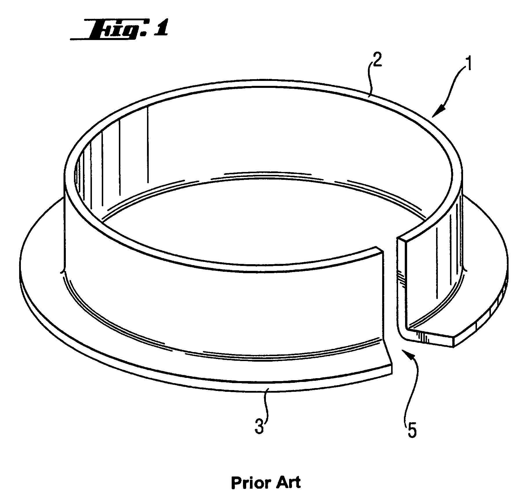
Flanged bushes with gaps can only be fitted using special tools, with which the flanged bush is compressed through the application of considerable force, wherein the flanged bush may possibly also warp, causing damage to the flanged bush.
Relatively small flanged bushes, which are transported in large numbers in cartons as loose cargo, may become hooked together, often resulting in a chain of several flanged bushes.
The buyer has to separate the flanged bushes laboriously and generally by hand before fitting them.
The disadvantage of this method is that welding is more expensive than bending of the bush edge.

Method used


Image

  • Flange sleeve, method for the production thereof and bending tool for producing flanges on a sleeve
  • Flange sleeve, method for the production thereof and bending tool for producing flanges on a sleeve
  • Flange sleeve, method for the production thereof and bending tool for producing flanges on a sleeve

Examples


Embodiment Construction

[0038]FIG. 1 shows a conventional flanged bush 1, which comprises a cylindrical bush body 2 and a single flange 3 formed thereon, having been produced by bending of the bush edge. As a result of the production process, the flanged bush 1 comprises a considerable butt gap 5.

[0039]FIG. 2 is a plan view of a flanged bush 10 according to the invention, produced by the method according to the invention. This flanged bush 10 likewise has a cylindrical bush body 12 and a single flange 13, which comprises material-displacing recesses 16 on the inner surface 14 of the flange 13 at a plurality of equidistant points in the circumferential direction. In the embodiment of FIG. 2 shown here, the material-displacing recesses are semi-circular in form, such that the recesses widen radially form the inside outwards. The recesses are applied in such a way that they extend as far as into the outer edge 15 of the flange 13. The flanged bush 10 exhibits a closed butt joint 11.

[0040]FIG. 3 is a plan view...


PUM

PropertyMeasurementUnit
Widthaaaaaaaaaa

Abstract

A flange sleeve comprising at lest one flange formed thereon, having no gap at the joint or having a controllably adjusted width of the gap at the joint. The flange has two crowding recesses at least in the metal coating thereof in at least two points distributed over the flange in the direction of the periphery. According to the method for producing the flange sleeves, the edge of the flange is bent. At least two crowding recesses in at least two points distributed over the flange in the direction of the periphery are made at least in the metal coating thereof, the recesses preferably being made by bending the edge of the sleeve. The invention also relates to a bending tool and a bending device.

Description

BACKGROUND OF THE INVENTION[0001]1. Technical Field[0002]The invention relates to a flanged bush, in particular a flanged bush for plain bearings with at least one flange formed thereon, and to, a method for the production thereof and a bending die.[0003]2. Related Art[0004]Flanged bushes, which comprise either one or two flanges, are known in a very wide range of sizes, with diameters ranging from centimeters to decimeters. The materials used depend on the intended application, wherein the bush material may be of single- or multilayer construction. Single-layer bushes are known as solid bushes. Bushes of multilayer construction generally comprise a backing material and an overlay. The overlay may consist of a metal alloy or plastics. The invention relates to all flanged bushes, irrespective of their dimensions, intended purpose and the materials used, with the one reservation that the flanged bushes have to comprise at least one metallic layer.[0005]To produce flanged bushes, an ed...

Claims


Application Information

Patent Timeline
IPC IPC(8): B21D31/00F16C33/14B21D11/08B21D19/08B21D53/10F16C17/10
CPCB21D11/08B21D19/08F16C17/10B21D53/10Y10T29/49673F16C33/14F16C2220/42
Inventor KIRCHHOF, KLAUSVALASIADIS, KONSTANTINOS
Owner FEDERAL MOGUL WIESBADEN
Learn More