
Ratchet mechanism for the headband of protective headgear used in high temperature environments

a ratchet mechanism and high temperature technology, applied in the direction of snap fasteners, buckles, protective garments, etc., can solve the problems of inability to perform the ratchet mechanism as intended, the risk of imprecise or flawed operation of the rack and pinion arrangement, and the remaining problem of such ratchet mechanisms

Active Publication Date: 2007-02-13
E D BULLARD
View PDF8 Cites 150 Cited by
  • Summary
  • Abstract
  • Description
  • Claims
  • Application Information

AI Technical Summary

Benefits of technology

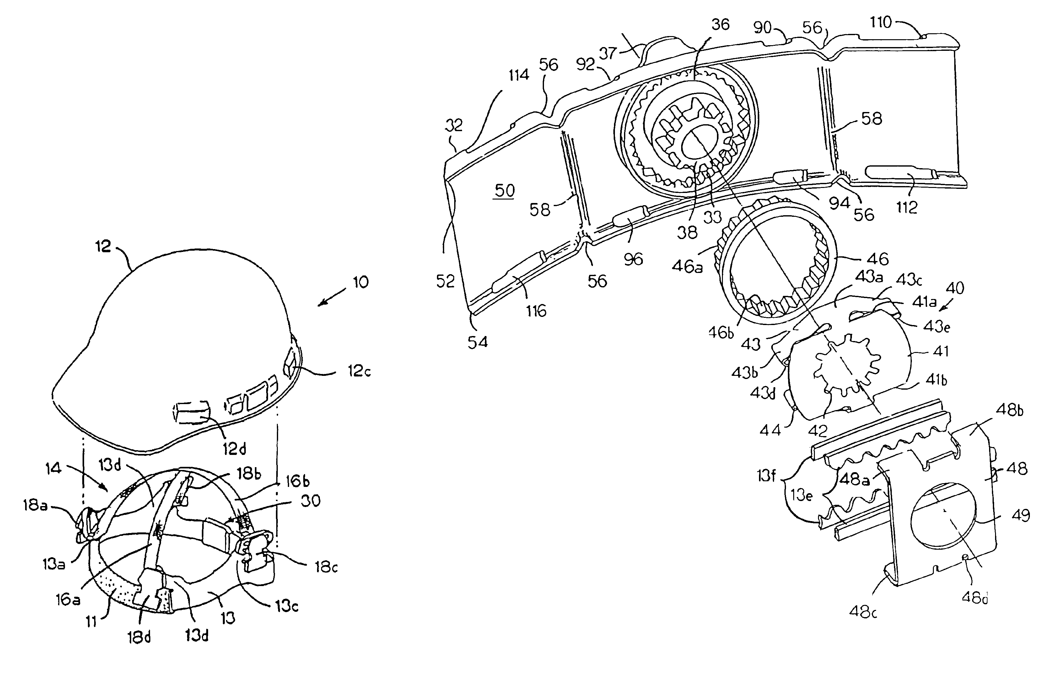
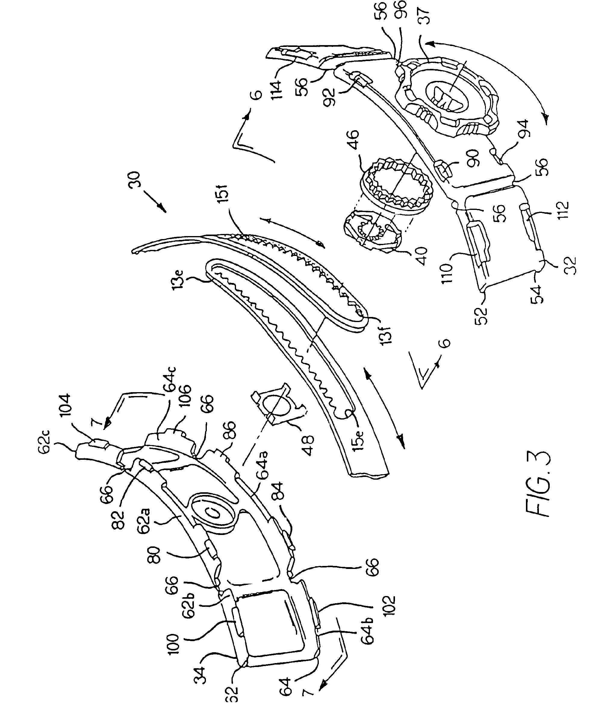
[0014]The present invention is a ratchet mechanism for the headband of a protective helmet or other headgear that is designed to function in high-temperature environments, while still allowing for ready adjustment of the size and fit of the headband. In this regard and as described above, a hard hat or similar protective helmet generally includes a substantially rigid shell, a head band, and a suspension comprised of two or more intersecting straps. A ratchet mechanism is then used to adjust the size of the headband, specifically through engagement of a rotational element with rack gears defined by the overlapping rear end portions of the headband to cause lateral movement of the overlapping rear end portions of said headband with respect to one another.
[0017]In this regard, an insert, also preferably manufactured from metal, is received and retained in one of the housing sections. The insert has an inner circumferential surface that defines a ring gear. Accordingly, the spring teeth of the spring assembly extend from each of the arch portions, mating with and engaging the teeth of the ring gear defined by the insert, locking the position of the rotational element, and thus the rear end portions of the headband relative the housing. However, when the adjustment knob and the rotational element are manually turned by a wearer, the spring teeth are forced over the teeth of the ring gear, with the flexion of the arch portions at the joints between the central portions and the respective appendages allowing for such movement of the spring teeth over the teeth of the ring gear. In other words, by imparting a sufficient torque on the rotational element, the wearer can overcome the spring force and effectuate lateral movement of the overlapping rear end portions of the headband relative to one another.
[0018]Accordingly, the spring assembly and insert allow for ready adjustment of the size and fit of the headband. However, since these components are preferably manufactured from metal, they do not suffer from the same warping problems associated with prior art plastic constructions, and therefore, the ratchet mechanism continues to function properly even in high-temperature environments. At the same time, the housing sections, the rotational element, and other components can still be made of polypropylene or a similar plastic material, which is important for purposes of flexibility and comfort.

Problems solved by technology

However, because the spring assembly has at least one spring tooth projecting radially and adapted for mating with radially projecting teeth of the ring gear assembly, the position of the rear end portions of the headband is essentially locked absent manipulation of the adjustment knob by the wearer.
However, the rack and pinion arrangements described in the prior art are generally comprised of a number of individual parts, requiring labor-intensive assembly and also increasing the risk of imprecise or flawed operation of the rack and pinion arrangement.
However, there is a remaining problem associated with such ratchet mechanisms.
In high-temperature environments, such as when the protective helmet is part of a firefighter's helmet, the ratchet mechanism may not perform as intended due to warping of the plastic components.

Method used


Image

  • Ratchet mechanism for the headband of protective headgear used in high temperature environments
  • Ratchet mechanism for the headband of protective headgear used in high temperature environments
  • Ratchet mechanism for the headband of protective headgear used in high temperature environments

Examples


Embodiment Construction

[0036]The present invention is a ratchet mechanism for the headband of a protective helmet or other headgear that is designed to function in high-temperature environments, while still allowing for ready adjustment of the size and fit of the headband.

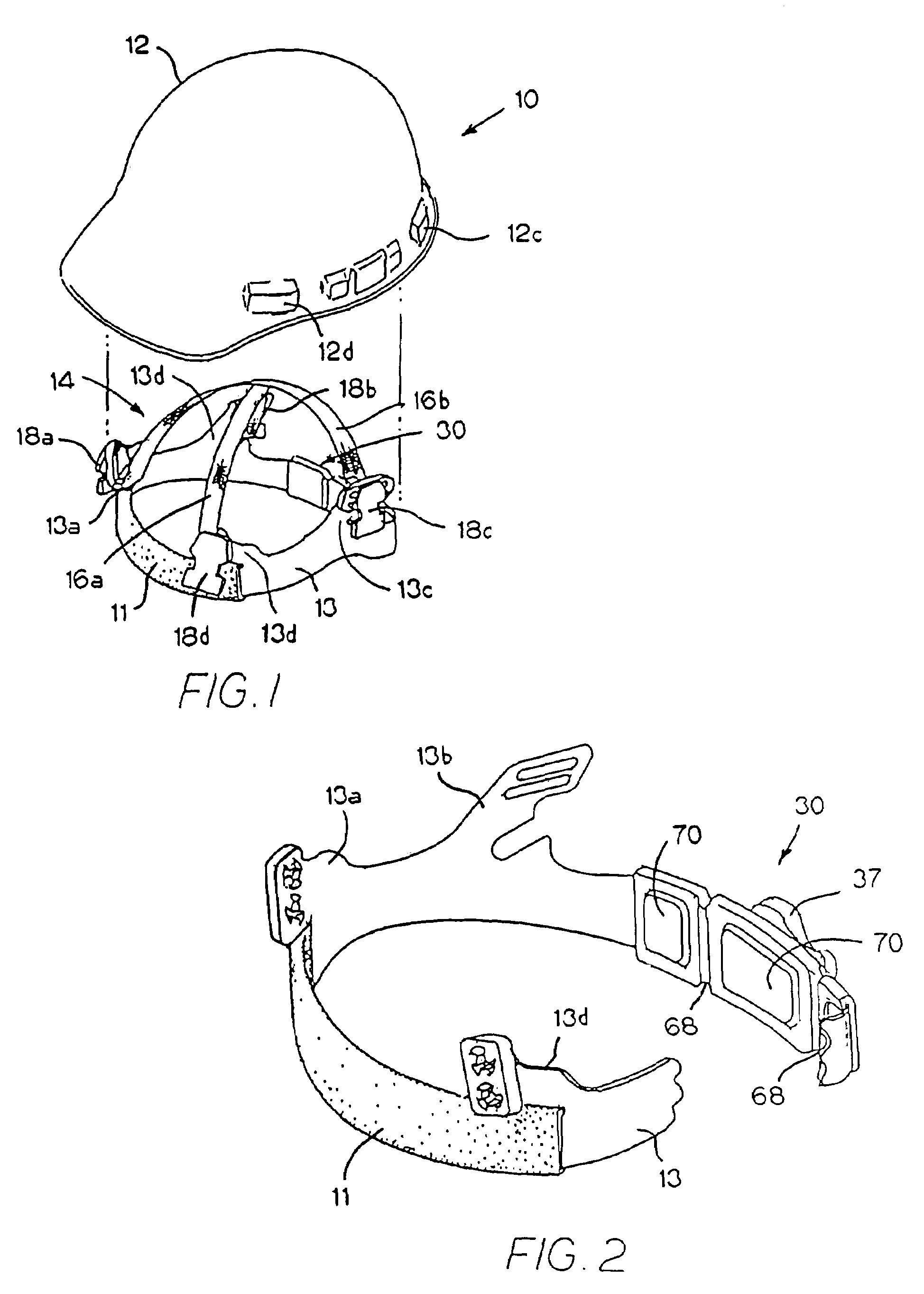
[0037]FIG. 1 is an exploded perspective view of an exemplary hard hat 10 that includes a ratchet mechanism made in accordance with the present invention. As shown, this hard hat 10 generally includes: a substantially rigid shell 12 shaped to protect the wearer's head, said shell 12 defining a bottom opening and an internal cavity for receiving the wearer's head; a headband 13 with an absorbent brow pad 11; and a suspension 14. In this exemplary embodiment, the hard hat 10 has a 4-point suspension 14 comprising two intersecting straps 16a, 16b. A key 18a, 18b, 18c, 18d is secured to each end of each of the straps 16a, 16b. Thus, to secure the suspension 14 to the shell 12 of the hard hat 10, the shell 12 includes four key sockets spaced a...


PUM


Abstract

A ratchet mechanism for the headband of a protective helmet or other headgear is designed to function in high-temperature environments, while still allowing for ready adjustment of the size and fit of the headband. In this regard, the ratchet mechanism includes a rotational element that has a pinion adapted to mate with and engage the respective rack gears of the overlapping rear end portions of the headband, such that rotation of the rotational element causes lateral movement of the overlapping rear end portions with respect to one another. A spring assembly associated with the rotational element engages a ring gear defined by an insert received and retained in the housing so as to resist rotation of the rotational element relative to said housing sections. Since the spring assembly and insert are preferably manufactured from metal, they do not suffer from warping problems, and therefore, the ratchet mechanism continues to function properly even in high-temperature environments.

Description

CROSS-REFERENCE TO RELATED APPLICATIONS[0001]The present application is a continuation-in-part of U.S. patent application Ser. No. 10 / 899,467 filed Jul. 26, 2004, now U.S. Pat. No. 7,000,262; and is a continuation-in-part of U.S. patent application Ser. No. 10 / 930,633 filed Aug. 31, 2004, now U.S. Pat. No. 7,043,772, the entire disclosures of which are incorporated herein by reference.BACKGROUND OF THE INVENTION[0002]The present invention relates to a ratchet mechanism for the headband of a protective helmet or similar headgear, a mechanism that allows for adjustment of the size and fit of the headband.[0003]Protective helmets are commonly worn in the industrial workplace to prevent or reduce the likelihood of head injuries. The hard hat is the most common and well-recognized protective helmet. A hard hat consists of three primary components—a shell, a headband, and a suspension system—which cooperate to reduce the potential for injury by attenuating some translational energy of the...

Claims


Application Information

Patent Timeline
Patent Type & Authority Patents(United States)
IPC IPC(8): A42B1/22
CPCA42B3/145Y10T24/2187
Inventor SCHERER, PAUL T.
Owner E D BULLARD
Learn More