
Crimping connection design system using multilayer feedforward neural networks

a neural network and connection technology, applied in the field of design support systems, can solve the problems of long design period, long design period, and increase design costs, and achieve the effect of short period of tim

Active Publication Date: 2007-02-06
YAZAKI CORP
View PDF13 Cites 10 Cited by
  • Summary
  • Abstract
  • Description
  • Claims
  • Application Information

AI Technical Summary

Benefits of technology

The invention is a design support system that helps designers easily design connections between a conductor and a connector terminal. The system uses an estimation unit that can learn from known connection data and create a rough value of unknown connection data based on the input of known connection data. This estimation unit can be a multilayer feedforward neural network or a C / W estimation unit. The system can also take into account factors like crimp width, crimp height, adhesion force, and contact resistance when estimating the unknown connection data. Overall, the system helps designers create connections more quickly and accurately without relying on their experience.

Problems solved by technology

Therefore, when a person who is less experienced in design attempts to design a connection, there arises consumption of a longer time until a desired connections implemented.
This in turn renders a design period longer and adds to design costs.

Method used


Image

  • Crimping connection design system using multilayer feedforward neural networks
  • Crimping connection design system using multilayer feedforward neural networks
  • Crimping connection design system using multilayer feedforward neural networks

Examples


first embodiment

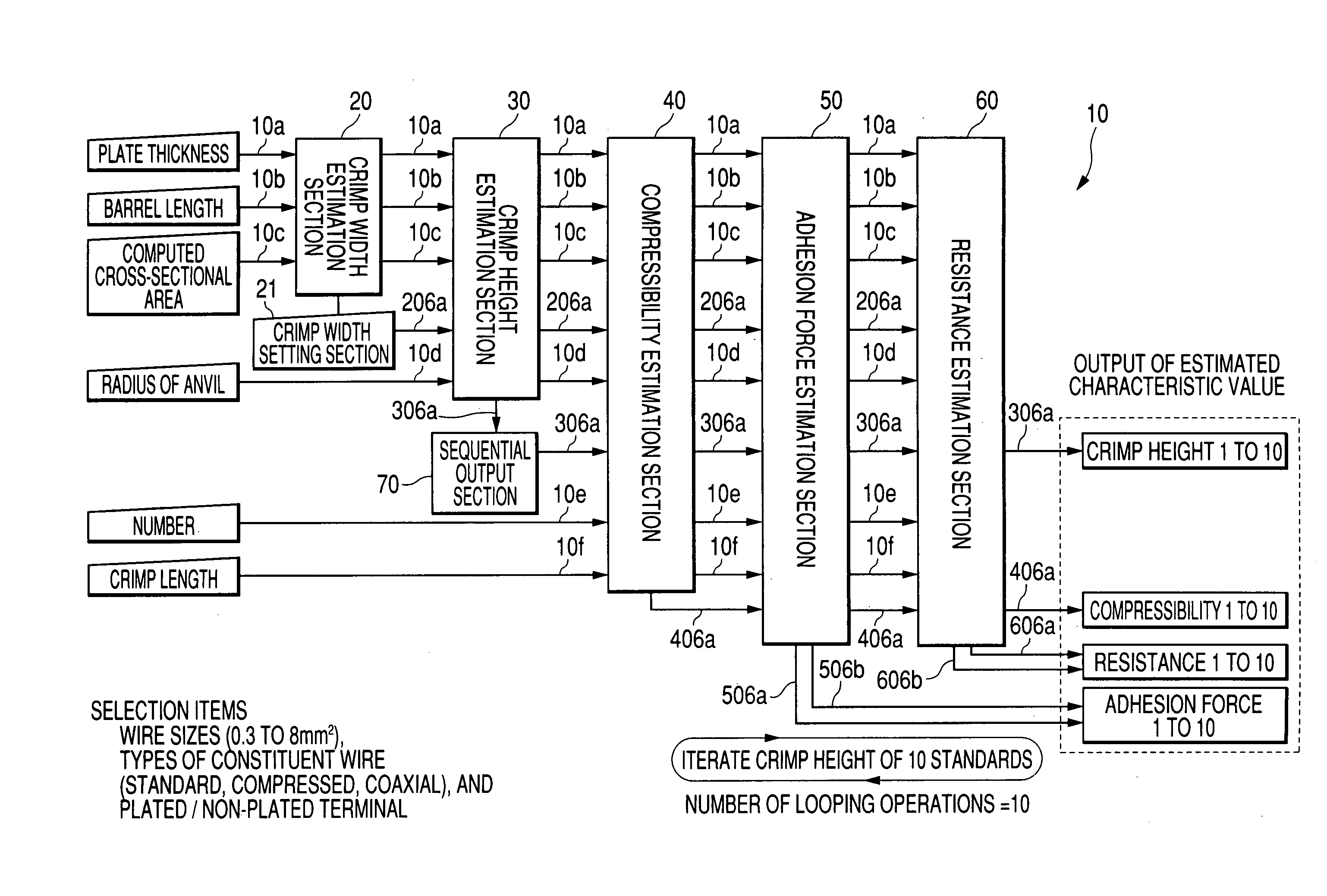
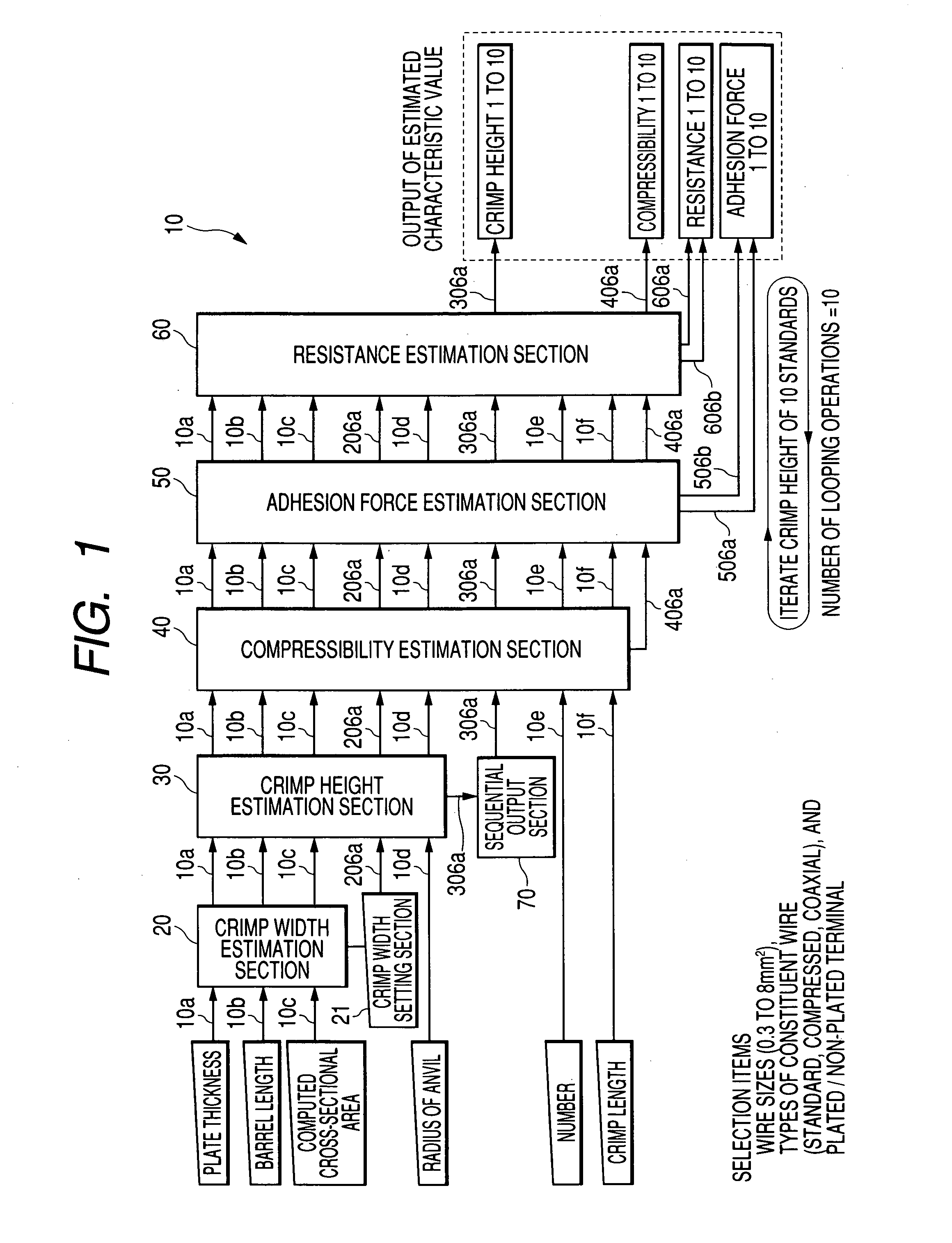
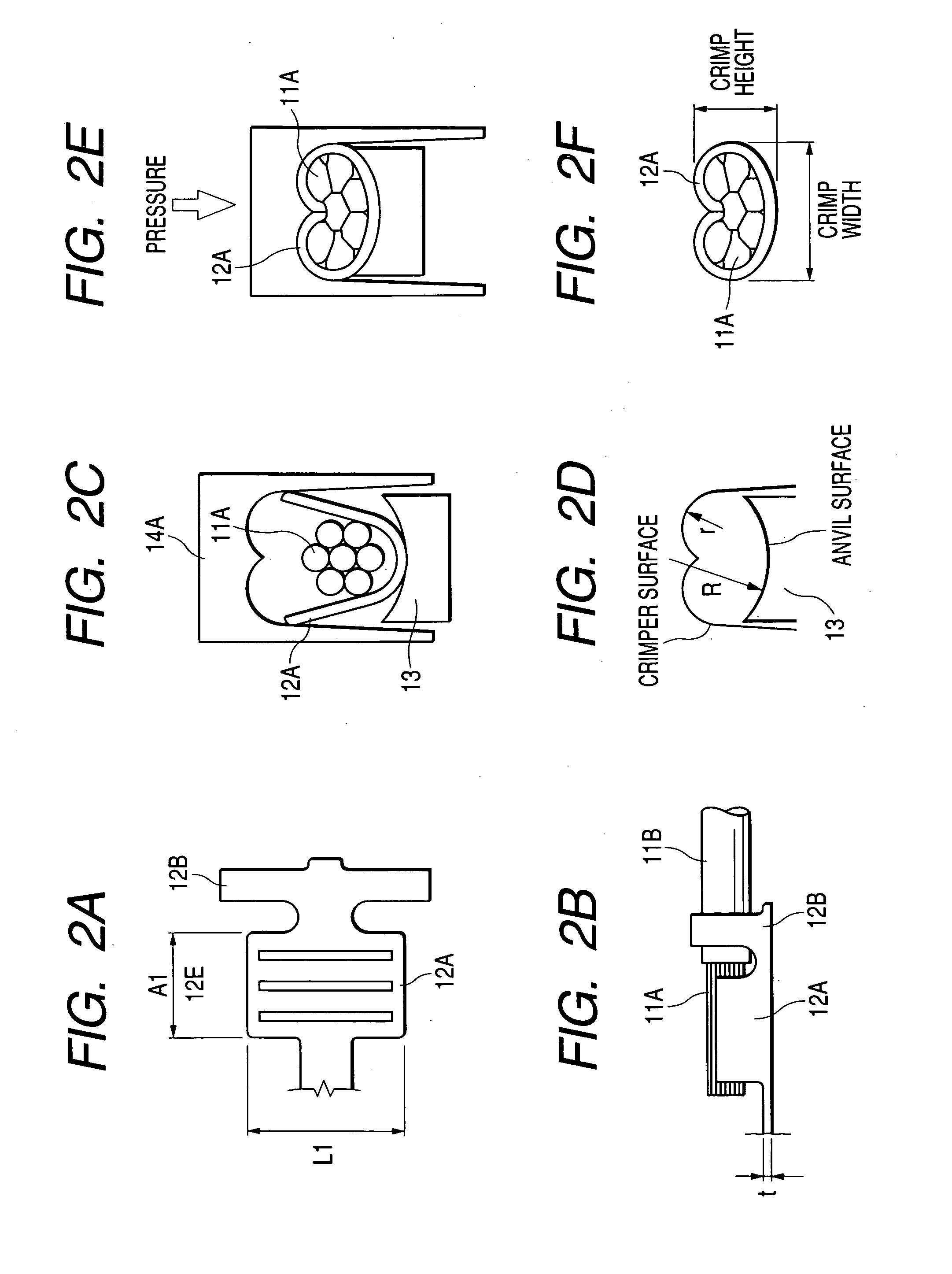
[0077]A first embodiment of the invention will be described by reference to the drawings. FIG. 1 is a view showing a first embodiment of a design support system 10 of the invention. As shown in FIGS. 2A to 2F, the design support system 10 is a system for supporting the design of connection by preliminarily estimating connection data pertaining to the design of unknown connection parameters, such as a crimp width C / W, a crimp height C / H, the compressibility of the conductor 11A in a crimping direction, and adhesion force and contact resistance existing between the conductor 11A and the connector terminal 12, prior to actual crimp connection of the conductor 11A, such as a wire or cable, to the connector terminal 12.

[0078]As illustrated, the design support system 10 has a C / W estimation section 20 (i.e., C / W estimation unit) formed from a multilayer feedforward neural network; a C / H estimation section 30 (i.e., C / H estimation unit); a compressibility estimation section 40 (i.e., compr...

second embodiment

[0121]Next, a second embodiment of the invention will be described. FIG. 7 is a view showing the second embodiment of the design support system 10. As shown in FIGS. 8A and 8B, the design support system 10 is a system which, at the time of connection of the conductor 11A sheathed with the insulation cladding 11B into the slot 12D formed in the connector terminal 12 by means of press-fitting, supports the design of a connection by previously estimating connection data pertaining to unknown connection design, such as a slot width W, a crimp height “l” which is a height from a base T of a slot 12D to the center of the conductor 11A, crimp load exerted on the conductor 11A in the direction of press-fitting, and withdrawal force and contact resistance exerted between the conductor 11A and the connector terminal 12 prior to actual press-fitting connection.

[0122]As illustrated, the design support system 10 has a slot width estimation section 80 (i.e., slot width estimation unit) formed fro...


PUM

PropertyMeasurementUnit
widthaaaaaaaaaa
thicknessaaaaaaaaaa
compressibilityaaaaaaaaaa

Abstract

Estimation sections which have beforehand learned a relationship between known connection data pertaining to connection design and unknown connection data pertaining to connection design for the known connection data estimate the unknown connection data for the known connection data in accordance wit an input of the known connection data, on the basis of the result of learning. The respective estimation sections are formed from a multilayer feedforward neural network in which layers constituted of a plurality of neurons are coupled together in a direction in which the layer runs from an input layer to an output layer by way of an intermediate layer.

Description

BACKGROUND OF THE INVENTION[0001]The invention relates to a design support system, and more particularly, to a design support system which preliminarily estimates unknown connection data prior to actual connection of a conductor to a connector terminal, to thereby support the design of a connection.[0002]A method for caulking and crimping a conductor by means of, e.g., a barrel provided on a connector terminal, and a method for press-fitting a conductor sheathed with an insulation cladding into a slot formed in the connector terminal have hitherto been available as a method for electrically connecting a conductor to a connector terminal.[0003]First, a method for connecting a conductor to a connector terminal by means of crimping will now be described. The connector terminal used for crimping connection usually assumes constructions such as shown those in FIGS. 2A and 2B. As illustrated, a connector terminal 12 has a conductor barrel 12A and an insulator barrel 12B.[0004]As shown in ...

Claims


Application Information

Patent Timeline
Patent Type & Authority Patents(United States)
IPC IPC(8): G06E1/00G06F17/50G06N3/00H01R43/048
CPCG06F17/50Y10T29/532Y10T29/53209Y10T29/49181Y10T29/49174Y10T29/49151G06F30/00
Inventor KAKUHARI, NOBUHIROITO, NAOKI
Owner YAZAKI CORP
Learn More