
Chip-to-chip interface for 1000 base T gigabit physical layer device

Inactive Publication Date: 2007-02-06
MARVELL ASIA PTE LTD
View PDF25 Cites 16 Cited by
  • Summary
  • Abstract
  • Description
  • Claims
  • Application Information

AI Technical Summary

Benefits of technology

[0020]It is a further object of the present invention to provide an interface between which reduces the number of pins or connections.
[0021]It is an additional object of the present invention to provide a system to efficiently control the auto-negotiated data rate.SUMMARY OF THE INVENTION

Problems solved by technology

The higher number of pins result in a larger die, a larger package, a more complicated integrated circuit and higher costs, particularly at the higher data transfer rates.
However, design of such circuit is difficult as the length of the traces and impedances between the traces must match for good signal integrity at this higher frequency.
This results in a more costly and complicated integrated circuit.
Traditional techniques either requires higher pin counts and complicated board routing.

Method used


Image

  • Chip-to-chip interface for 1000 base T gigabit physical layer device
  • Chip-to-chip interface for 1000 base T gigabit physical layer device
  • Chip-to-chip interface for 1000 base T gigabit physical layer device

Examples


Embodiment Construction

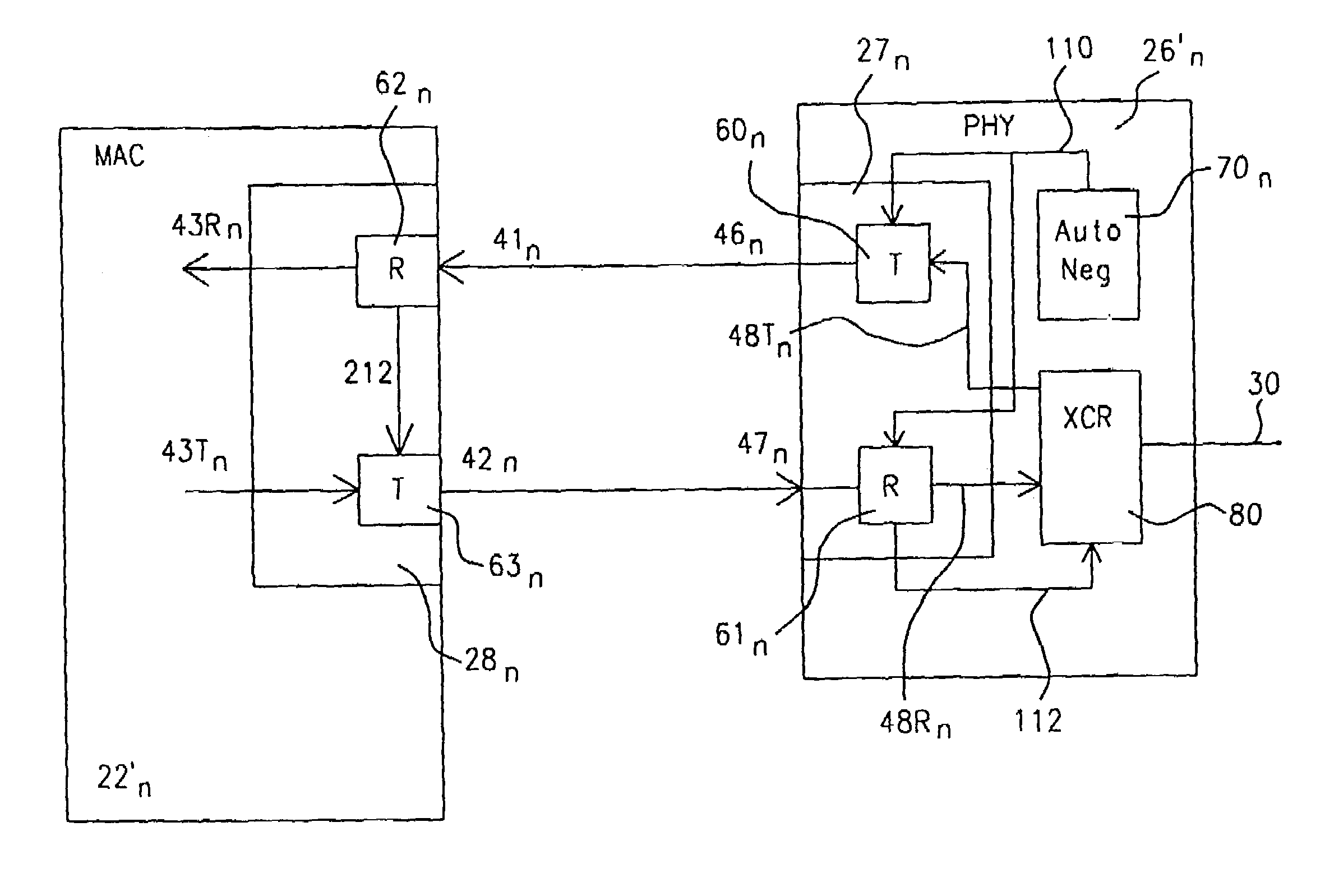
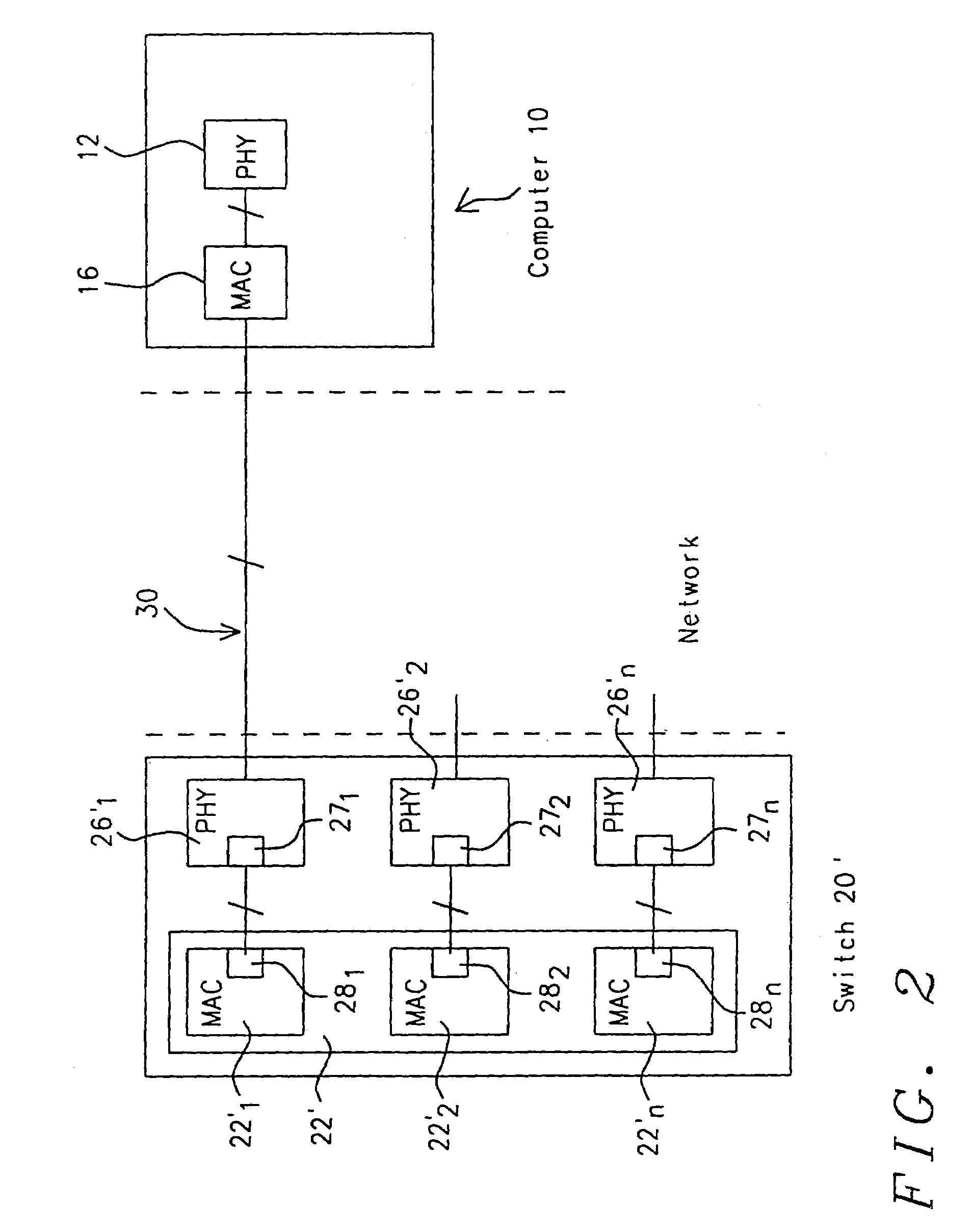
[0039]Referring to FIG. 2, shown therein is a preferred embodiment of the present invention. As shown therein, a computer 10 is connected to a first port of switch 20 via a communications channel, such as, twisted pair cable 30. Switch 20′ may comprise 24 ports, to allow computer 10 to communicate with other computers, peripherals, network appliances and other networks.

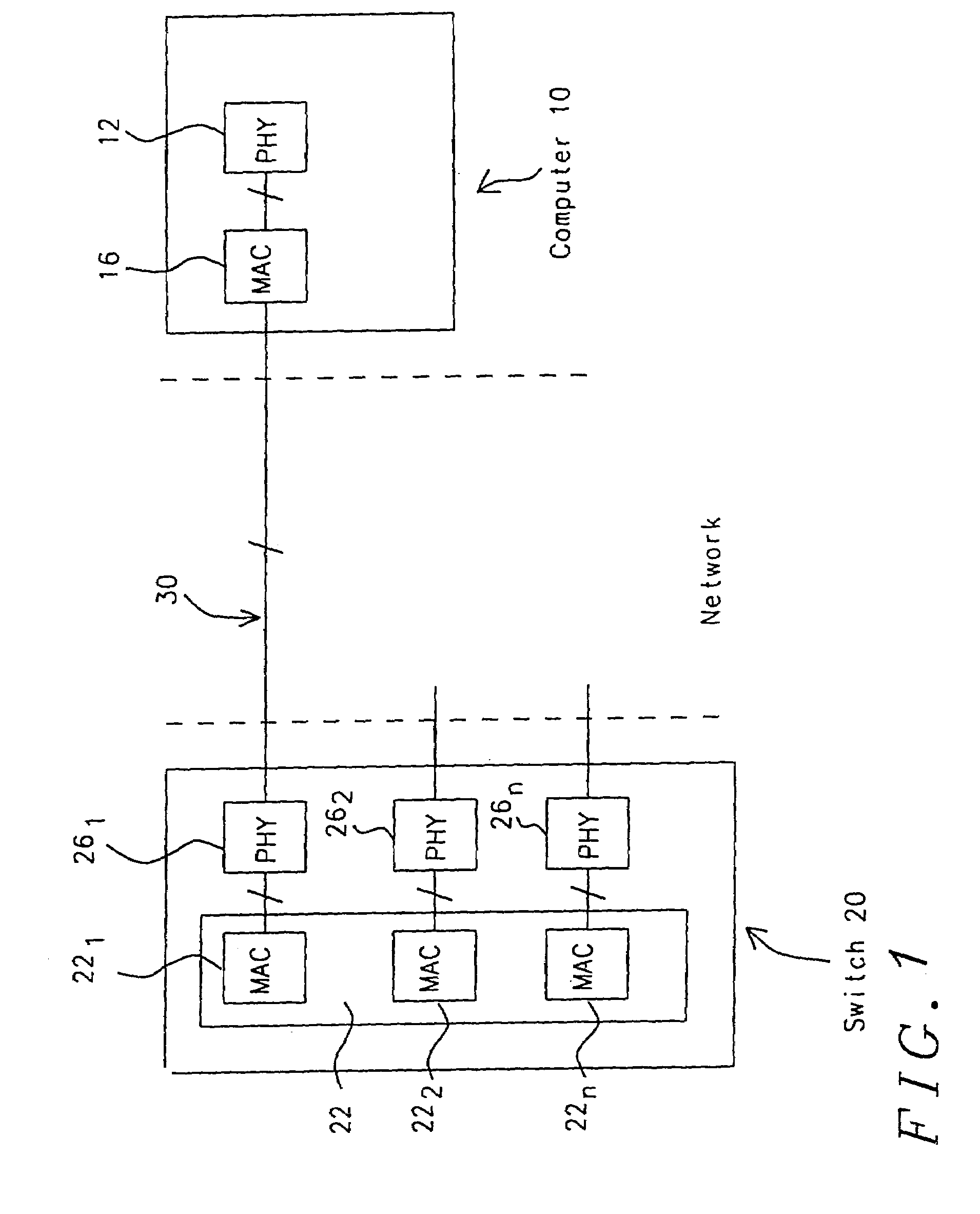
[0040]Computer 10 comprises a media access controller or (MAC) 12 and physical layer interface (PHY) or transceiver 16, which are connected to each other in accordance with an interface, such as, MII or GMII discussed above. Media access controller 12, computer 10, and PHY 16 are similar to those described above, therefore no further discussion is provided herein. As will be appreciated by one of ordinary skill in the art, communication channel 30 may be implemented using a variety of techniques, for example wired, wireless, radio frequency, optical and the like.

[0041]Switch 20′ comprises n ports. Each of the n ports ...


PUM


Abstract

A network device includes a first integrated circuit and a second integrated circuit. The first integrated circuit includes a media access controller and a first serializer interface in communication with the media access controller. The second integrated circuit includes a physical layer interface in communication with an external device. The second integrated circuit also includes a second serializer interface in communication with the physical layer interface and the first serializer interface. The second serializer interface communicates with the first serializer interface at a predetermined data transmission rate regardless of a negotiated transmission rate between the network device and the external device.

Description

CROSS REFERENCE TO RELATED APPLICATIONS[0001]This application is a continuation of U.S. patent application Ser. No. 09 / 501,556, filed Feb. 9, 2000, which is hereby incorporated by reference in its entirety.INCORPORATION BY REFERENCE[0002]The inventors incorporate IEEE Standard 802.3 in its entirety herein by reference.BACKGROUND OF THE INVENTION[0003]1. Field of the Invention[0004]This invention relates generally to an interface and switch for a high speed network, and more particularly to an interface and network switch capable of communicating at a nominal rate of up to 1 gigabit per second.[0005]2. Description of the Related Art[0006]Interconnections of and communications among computers, peripheral devices, Internet appliances (generally referred to as network clients hereinbelow) via computer networks are ubiquitous. Moreover as applications such as, multimedia, require higher data transfer rates there is a need for more robust and faster networks.[0007]Network switches facilit...

Claims


Application Information

Patent Timeline
IPC IPC(8): H04L12/66H04Q7/24H04L12/56H04L49/111
CPCH04L49/3054H04L47/25H04J3/18H04L12/2874H04L25/0262H04L49/351H04L69/24
Inventor SUTARDJA, SEHATLO, WILLIAM
Owner MARVELL ASIA PTE LTD
Learn More