
Adjustable regulated power device

a regulated power device and adjustable technology, applied in the direction of automatic control, process and machine control, instruments, etc., can solve the problems of insufficient control modes, inconvenient change of output voltage value, and insufficient safety of output voltage, so as to achieve high safety/reliability, low cost, and full function

Inactive Publication Date: 2007-02-06
WINBOND ELECTRONICS CORP
View PDF1 Cites 5 Cited by
  • Summary
  • Abstract
  • Description
  • Claims
  • Application Information

AI Technical Summary

Benefits of technology

The present invention provides an adjustable regulated power device that can fulfill digital inputs by a keyboard and control electronic potentiometers by a microprocessor to complete many functions, such as voltage adjustments, a feedback control, a current-limit protection, constant current / current-limit value adjustments. The device also features a low cost, a high safety / reliability, full functions, convenient operations, high voltage / current adjustment accuracies and a compact size. Additionally, the invention provides an adjustable regulated switching power device that can fulfill digital inputs by a keyboard and control electronic potentiometers by a microprocessor to complete many functions, such as voltage adjustments, a feedback control, a current-limit protection, constant current / current-limit value adjustments. The device also features a low cost, a high safety / reliability, full functions, convenient operations, high voltage / current adjustment accuracies and a compact size. Furthermore, the invention includes a comparison device formed by a sampler and a comparator for sampling the current with the output voltage to produce a sampling signal and comparing it with a base voltage from the second potentiometer, followed by outputting a comparison result.

Problems solved by technology

The shortage thereof is that the above-mentioned circuits are in full analog control modes.
Then, the user needs to adjust a potentiometer to get a required output voltage with a quite inconvenience.
In addition, a more problematic shortage is that an accidental touch with the adjustment potentiometer during operations would change the output voltage value.
Therefore, such control modes are not enough for safety.
A faulted output voltage even damages the connected load device.
However, the shortages with such method are an oversized circuit structure and a higher cost, which make it hard for popular applications.

Method used


Image

  • Adjustable regulated power device
  • Adjustable regulated power device
  • Adjustable regulated power device

Examples


Embodiment Construction

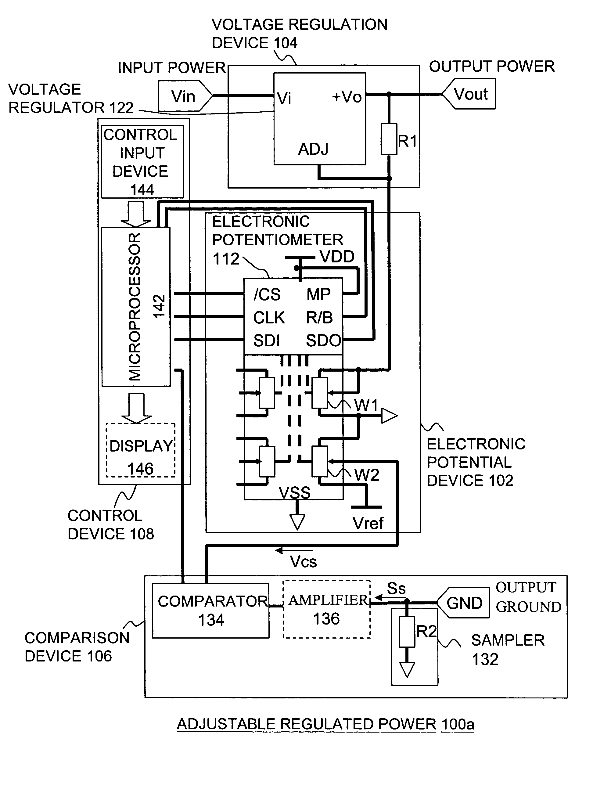
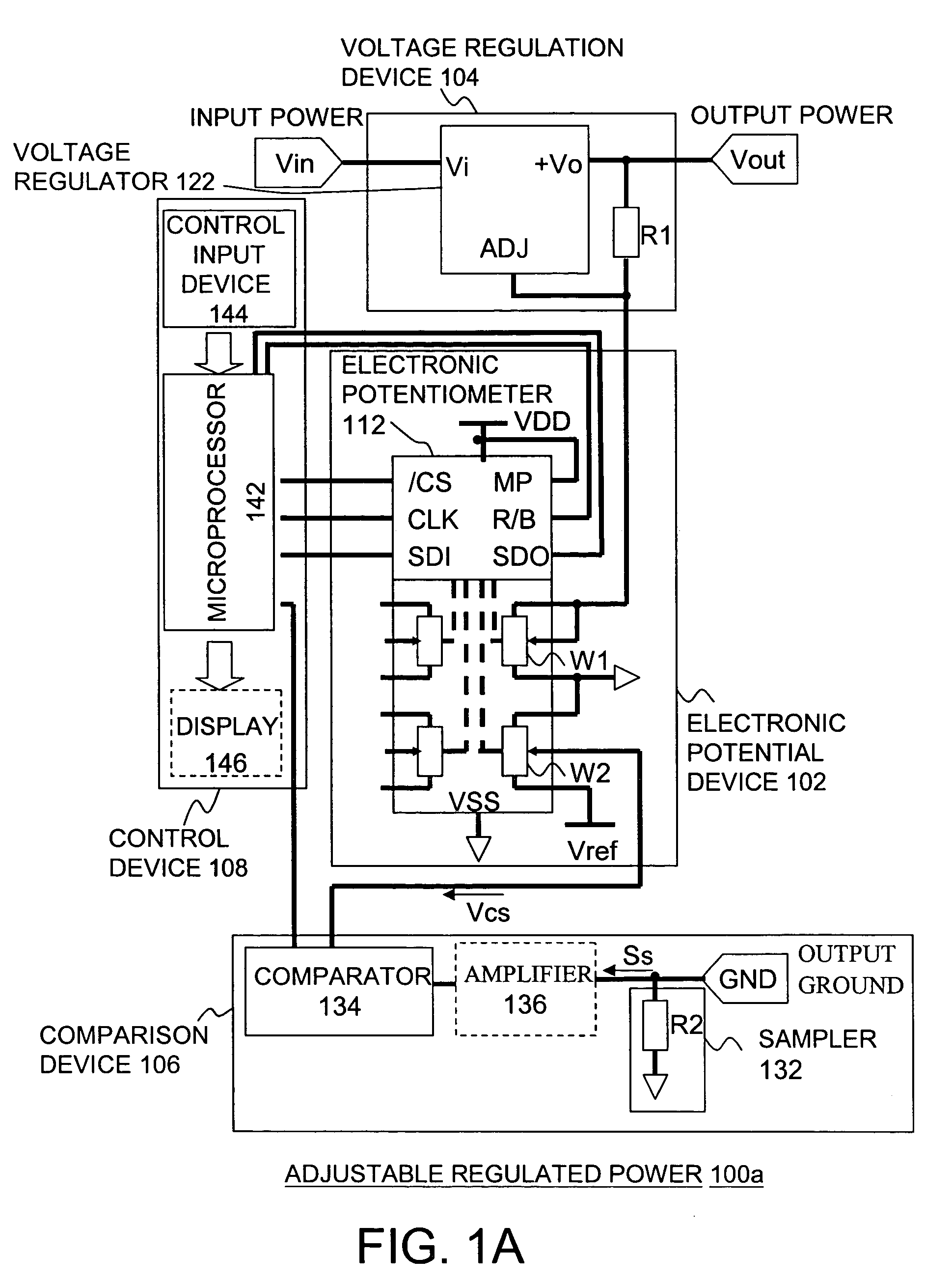
[0019]FIG. 1A is a schematic circuit drawing of an adjustable regulated power device according to an embodiment of the present invention. Referring to FIG. 1A, the adjustable regulated power device 100a includes, for example, an electronic potential device 102, a voltage regulation device 104, a comparison device 106 and a control device 108.

[0020]The electronic potential device 102 includes, for example, an electronic potentiometer 112. In an embodiment of the present invention, the electronic potentiometer 112 is, for example, an electronic potentiometer model WMS7204 (as shown in FIG. 1A, included of four sets of potentiometers) manufactured by Winbond Electronics Ltd. In addition, the electronic potentiometer can be an electronic potentiometer model WMS7202 (comprised of two sets of potentiometers) manufactured by Winbond Electronics Ltd., or any other kinds of electronic potentiometers. It is not limited to the one shown in any embodiments of the present invention. The electron...


PUM


Abstract

An adjustable regulated power device includes, for example, an electronic potential device, a regulated device and a control device. The electronic potential device includes an electronic potentiometer having a plurality of potentiometers. The regulated device includes a voltage regulator connected to an input power and at least one first potentiometer of the potentiometers. The first potentiometer forms a variable resistor used for adjusting an output voltage from the voltage regulator. The control device includes a microprocessor and a control input device used for receiving an input setting value. The microprocessor is connected to the control input device and the electronic potentiometer for receiving the setting value and controlling the electronic potentiometer according to the setting value.

Description

CROSS-REFERENCE TO RELATED APPLICATION[0001]This application claims the priority benefit of Taiwan application serial no. 94105746, filed on Feb. 25, 2005. All disclosure of the Taiwan application is incorporated herein by reference.BACKGROUND OF THE INVENTION[0002]1. Field of Invention[0003]The present invention relates to a regulated power device. In particular, it relates to an adjustable regulated power device with high voltage / current adjustment accuracies and a compact size.[0004]2. Description of the Related Art[0005]In the conventional technology, the output voltage from a voltage regulated power mostly is fixed. To fulfill an adjustable output voltage, it is usually to incorporate the conventional voltage regulated power with an additional adjustment potentiometer, or to use a resistance array voltage divider for rang-selected adjustments. These methods, however, are usually applicable to low-end products. The shortage thereof is that the above-mentioned circuits are in ful...

Claims


Application Information

Patent Timeline
Patent Type & Authority Patents(United States)
IPC IPC(8): G05B24/02
CPCG05F1/56
Inventor HUANG, GUANG-JIAN
Owner WINBOND ELECTRONICS CORP
Learn More