Laundry dryer having gas combustion apparatus

a technology of gas combustion apparatus and dryer, which is applied in the field of laundry dryers, can solve the problems of excessive elongation of flame formation, difficult control of blower, and catastrophic failure, and achieve the effect of preventing lifting and overheating conditions

Active Publication Date: 2007-02-06
LG ELECTRONICS INC
View PDF25 Cites 6 Cited by
  • Summary
  • Abstract
  • Description
  • Claims
  • Application Information

AI Technical Summary

Benefits of technology

[0015]It is another object of the present invention to provide a laundry dryer having a gas combustion apparatus, by which the length of a flame of gas combustion is reduced and the introduction of secondary air is increased.
[0016]It is another object of the present invention to provide a laundry dryer having a gas combustion apparatus, by which a main flame exiting a mixing pipe is separated into a plurality of resultant flames to facilitate a mixing of the flame with secondary air.
[0017]It is another object of the present invention to provide a laundry dryer having a gas combustion apparatus, by which a stable, high-temperature flame is produced while preventing backfiring.
[0019]It is another object of the present invention to provide a laundry dryer having a gas combustion apparatus, by which combustion is accelerated.
[0020]It is another object of the present invention to provide a laundry dryer having a gas combustion apparatus, by which lifting and overheating conditions are prevented.

Problems solved by technology

If the rotational speed of the blower 17 is too low, the resulting flame formation is excessively elongated.
Such control of the blower is difficult, and failure may be catastrophic.
The reduced contact area also results in incomplete combustion due to an insufficient supply of secondary air to the flame, which produces an elongated, yellow flame producing excessive amounts of soot and toxic gases such as CO, NOx, and SOx.
In addition, there is a tendency at the time of initial ignition by the spark plug 26 for the gas-and-air mixture within the mixing pipe 24 to escape from its outlet end, without combustion, thus lowering ignition capability.

Method used


Image

  • Laundry dryer having gas combustion apparatus
  • Laundry dryer having gas combustion apparatus
  • Laundry dryer having gas combustion apparatus

Examples


Embodiment Construction

[0033]Reference will now be made in detail to the preferred embodiment of the present invention, examples of which are illustrated in the accompanying drawings. Throughout the drawings, like elements are indicated using the same or similar reference designations where possible.

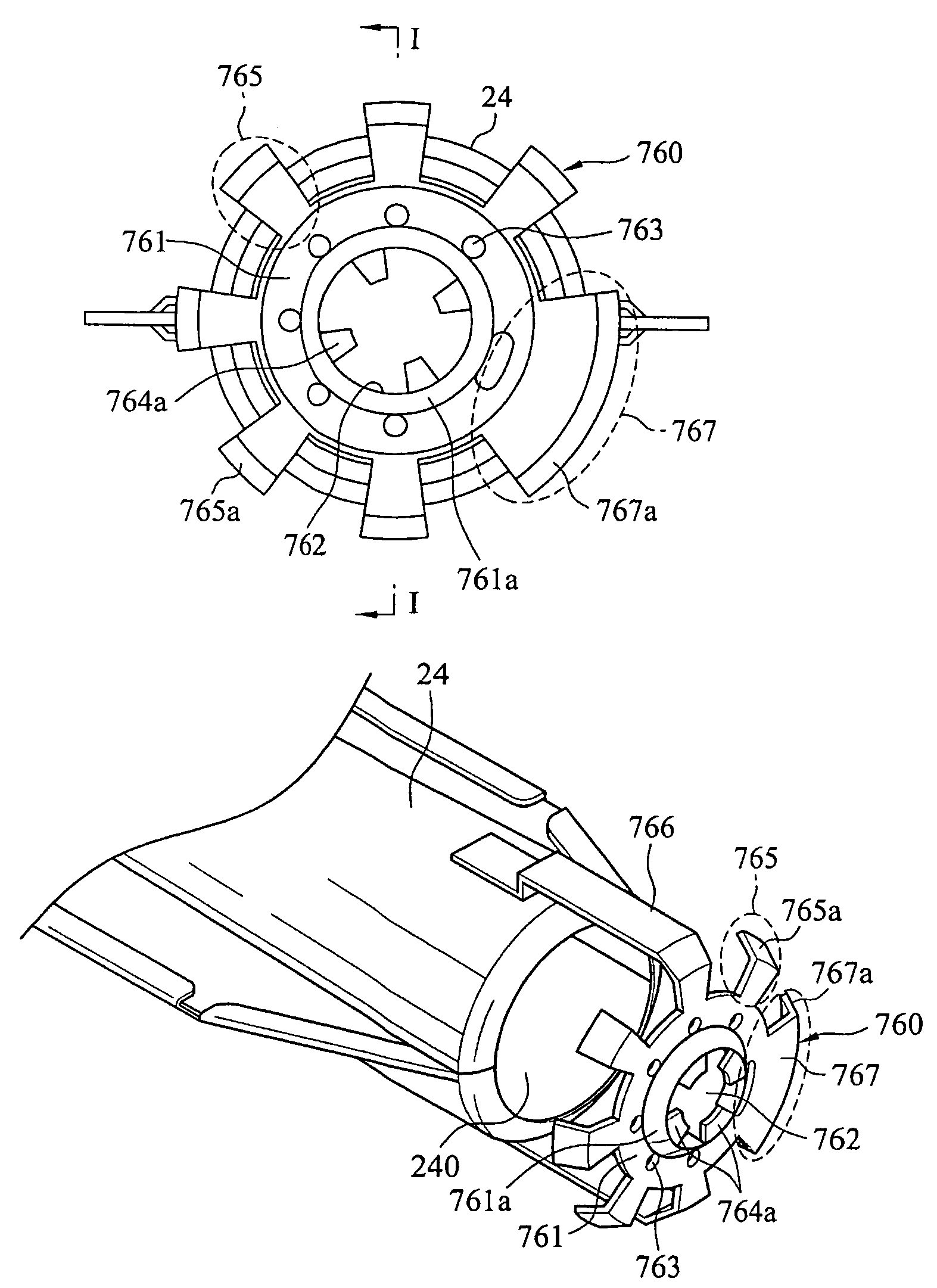
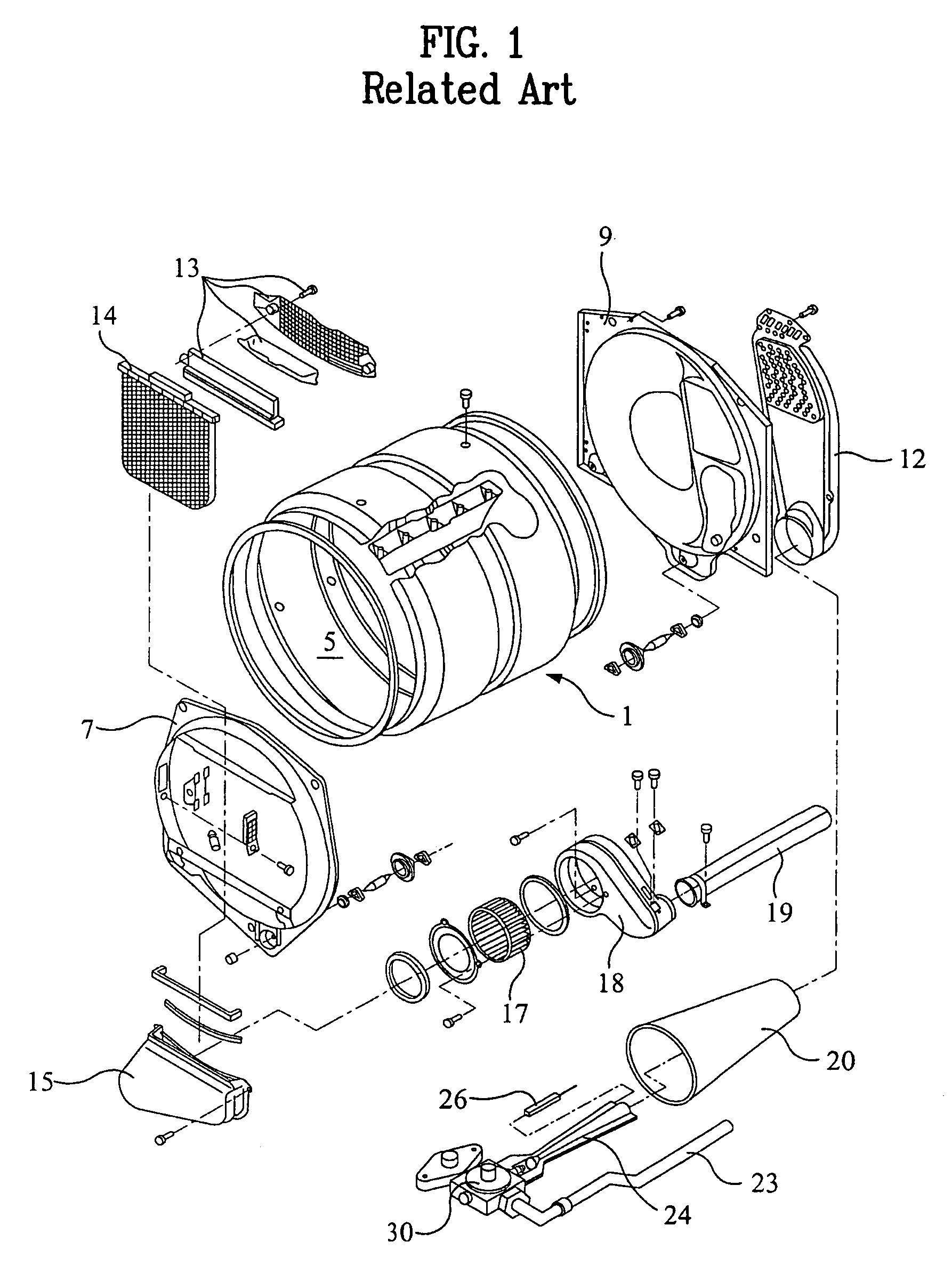
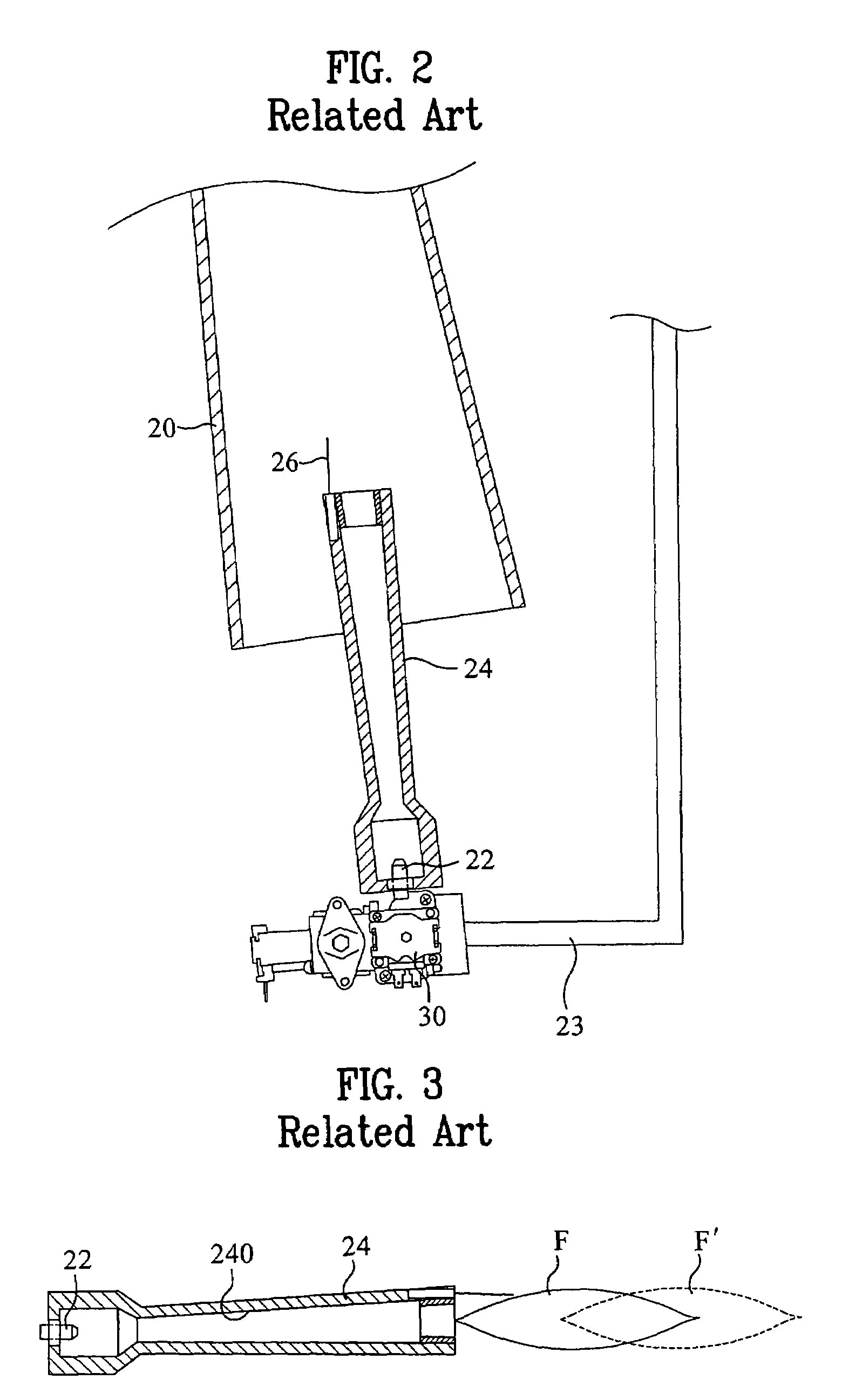
[0034]Referring to FIG. 4, illustrating a gas combustion apparatus for use in a laundry dryer according to the present invention, a gas supply pipe 23 for supplying gas is connected to a gas nozzle 22 from which the gas is injected into a mixing pipe 24 under the control of a valve 30 for controlling the amount of gas supplied to the gas nozzle. The mixing pipe 24, disposed in front of the gas nozzle 22, has a mixing passage 240 having tapered cross-section for mixing primary air with the gas injected from the gas nozzle. Thus, the gas-and-air mixture flows into the mixing pipe's smaller inlet end, along the mixing passage 240, and exits through its larger outlet end to be directed toward a guide funnel 20. An...


PUM


Abstract

A gas combustion apparatus of a laundry dryer is provided, by which an initial ignition power is improved to enhance an ignition property. The gas combustion apparatus includes a gas supply; a mixing pipe, having a mixing passage extending from an inlet end to an outlet end, for mixing the supplied gas with primary air, the primary air and gas entering the mixing passage at the inlet end and a gas-and-air mixture exiting the mixing passage at the outlet end; and a flame holder, disposed at the outlet end of the mixing pipe, for separating the gas-and-air mixture exiting the mixing pipe into a complex plurality of jetted streams.

Description

[0001]This application claims the benefit of Korean Application No. 10-2002-0077009 filed on Dec. 5, 2002, which is hereby incorporated by reference.BACKGROUND OF THE INVENTION[0002]1. Field of the Invention[0003]The present invention relates to a laundry dryer, and more particularly, to a laundry dryer having a gas combustion apparatus employing a flame holder for separating the flame exiting a mixing pipe.[0004]2. Discussion of the Related Art[0005]A typical laundry dryer performs drying using hot air, which is drawn into a drying chamber through an inlet duct, under the power of a blower installed adjacent an outlet pipe, to be discharged from the drying chamber via a lint-filtering unit. The hot air may be generated by means of an electric heater or gas combustion. A gas dryer employs a gas combustion apparatus.[0006]Referring to FIG. 1, illustrating major components of a gas-combustion laundry dryer according to a related art, a cylindrical drum 1 together with front and rear s...

Claims


Application Information

Patent Timeline
IPC IPC(8): F23D14/70F23D14/84D06F58/26F23D14/08
CPCF23D14/08D06F58/263F23D14/06
Inventor HAN, IN HEEJEONG, SEONG HAIPARK, SOO WON
Owner LG ELECTRONICS INC
Why Eureka
Try Eureka