
Divider barrier for roadway delineation

a technology of divider barriers and roadways, applied in roadway safety arrangements, traffic restrictions, roads, etc., can solve the problems of divider barriers being moved more severely to the side, the weight of vehicles not contributing to the fixation of divider barriers, etc., to facilitate insertion, assembly and disassembly operations, and assembly can be further simplified.

Inactive Publication Date: 2007-02-06
SPIG SCHUTZPLANKEN PRODN
View PDF11 Cites 6 Cited by
  • Summary
  • Abstract
  • Description
  • Claims
  • Application Information

AI Technical Summary

Benefits of technology

[0006]On the basis of the prior art, the invention is thus based on the object to improve the application of a divider barrier, to increase the restraining capacity, and in particular to reduce a lateral displacement in the event of an impact.
[0011]Suitably, the pin is constructed in the form of a cone section. This facilitates insertion in the receiving openings of a fishplate and thus assembly and disassembly operations.
[0012]Assembly can be further simplified by constructing the fishplates in symmetric relationship to their center transversal plane. The installation of the fishplates is thus independent on the arrangement of the receiving openings and on the position of the other threaded bores which assist in the securement of the fishplates upon the support plates. The fishplates can be used on the left as well as right side, i.e. on both sides of a divider member. The mirrored or symmetrical configuration of the fishplates also simplifies their manufacture.
[0015]To further safeguard the divider barrier against transversal displacement, friction-increasing means can be provided on the underside of the base bodies. Preferably, the friction-increasing means are formed by single-piece shoes which formfittingly embrace from below stringers provided on the underside of the base bodies. The shoes are made of elastomer, especially rubber or polyurethane. In addition, the shoes oppose a heat conduction from the divider barrier to the roadway surface. As a result, adverse heating of the road pavement or roadway surface is prevented. At the same time, the standing area of the stringers is increased and thus the surface pressure on the roadway surface is decreased so that impressions can be avoided. In particular, the friction-increasing means comply with the demands for a slightest possible lateral displacement in the event of an impact.

Problems solved by technology

Depending on the approach angle, there may be occasions when the wheel of an impacting motor vehicle is unable to fully contact the lower support plates so that the weight of the vehicle fails to contribute to the fixation of the divider barrier on the roadway.
As a result, the divider barrier may be displaced more severely to the side.

Method used


Image

  • Divider barrier for roadway delineation
  • Divider barrier for roadway delineation
  • Divider barrier for roadway delineation

Examples


Embodiment Construction

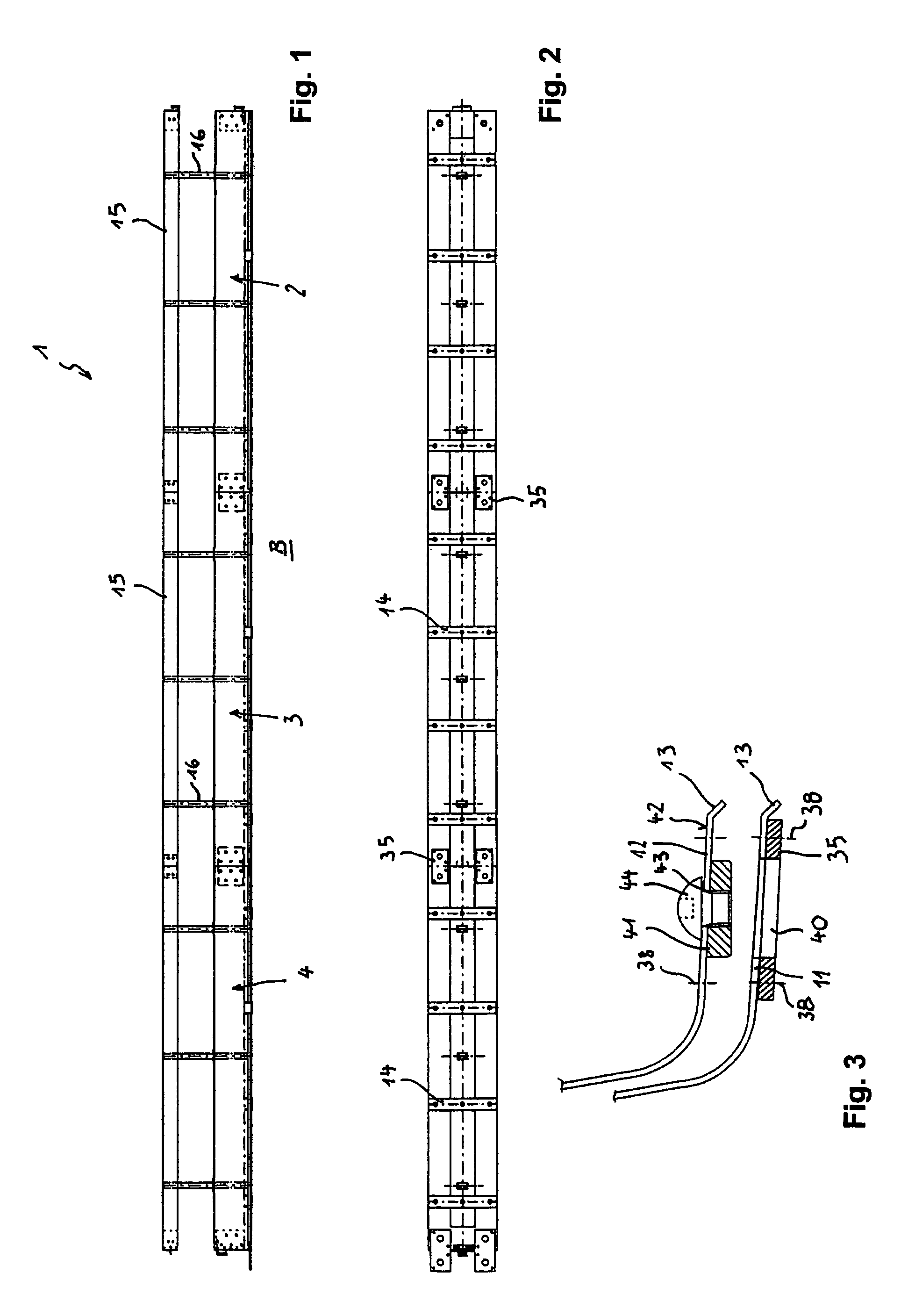
[0032]FIG. 1 shows a section of a divider barrier 1 of steel which is arranged as roadway delineation for example on a median strip between two lanes with two-way traffic.

[0033]The divider barrier 1 includes divider members 2, 3, 4 (see also FIGS. 4 to 6) which are detachably juxtaposed in longitudinal direction. Each divider member 2, 3, 4 has a housing-like base body 5 with slanted roof-shaped lateral collision plates 6, 7, a top plate 9 which connects the upper longitudinal edges 8 of the collision plates 6, 7, as well as the support plates 11, 12, which are connected in the form of flanges to the lower longitudinal edges 10 of the collision plates 6, 7 and extend from the base body 5 outwards. The marginal portions 13 of the support plates 11, 12 are slightly bent downwards. Bottom-side stringers 14, as shown in FIGS. 2 to 5, provide the support of the base bodies 5 of the divider members 2, 3, 4, on the ground.

[0034]Extending above the base body 5 at a distance thereto is a gui...


PUM


Abstract

A divider barrier 1 for roadway delineation includes detachably juxtaposed divider members 2, 3, 4. The divider members have each a housing-like base body 5 which can be placed on the ground and has slanted roof-shaped lateral collision plates 6, 7. Connected to the lower longitudinal edges 10 of the collision plates 6, 7 are support plates 11, 12 which extend from the base body 5 outwards. A guide bar 15 is provided above the base body 5 at a vertical distance thereto. Connecting means 18–21 are provided to detachably couple successive divider members 2, 3, 4 with one another. The support plates 11, 12 of two successive divider members 2, 3, 4 are detachably connected to one another by means of fishplates 35 on the underside, wherein each fishplate 35 is hereby fixed with its first end portion 36 under the support plate 11 of the one divider member 2, 3, 4 and with its second end portion 37 under the support plate 12 of the following second divider member 2, 3, 4. Each of the first end portion 11 as well as the second end portion 12 of each fishplate 35 has a receiving opening 40 for engagement of a pin 41 constructed of round configuration and secured under each of the support plates 11, 12. As a consequence of these pins 41, the divider barrier 1 is stiffened against lateral displacement.

Description

BACKGROUND OF THE INVENTION[0001]The invention relates to a divider barrier of steel for roadway delineation.[0002]A prior art divider barrier comprised of butt-joined divider members is described in EP 0 472 847 B1 or also DE 38 27 030 C2 and predominantly provided for mobile use in construction sites, for example.[0003]Known divider barriers have proven very useful and find application on many roadways in Europe. The divider barriers are very easy to assemble and to dismantle and provide very reliable roadway delineation with high restraining capacity. Depending on the approach angle, there may be occasions when the wheel of an impacting motor vehicle is unable to fully contact the lower support plates so that the weight of the vehicle fails to contribute to the fixation of the divider barrier on the roadway. As a result, the divider barrier may be displaced more severely to the side.[0004]Further, divider barriers have to meet different requirements established by various countri...

Claims


Application Information

Patent Timeline
IPC IPC(8): E01F13/00
CPCE01F15/025E01F15/088E01F15/085
Inventor SCHMITT, KARL-HEINZ
Owner SPIG SCHUTZPLANKEN PRODN
Learn More