
System and method for creating a display card

a display card and system technology, applied in the direction of meter-controlled dispensing apparatus, instruments, coin-freed apparatus, etc., can solve the problems of temporary pass, user waiting, identification card not being immediately available,

Inactive Publication Date: 2007-02-06
CCL LABEL INC
View PDF50 Cites 77 Cited by
  • Summary
  • Abstract
  • Description
  • Claims
  • Application Information

AI Technical Summary

Benefits of technology

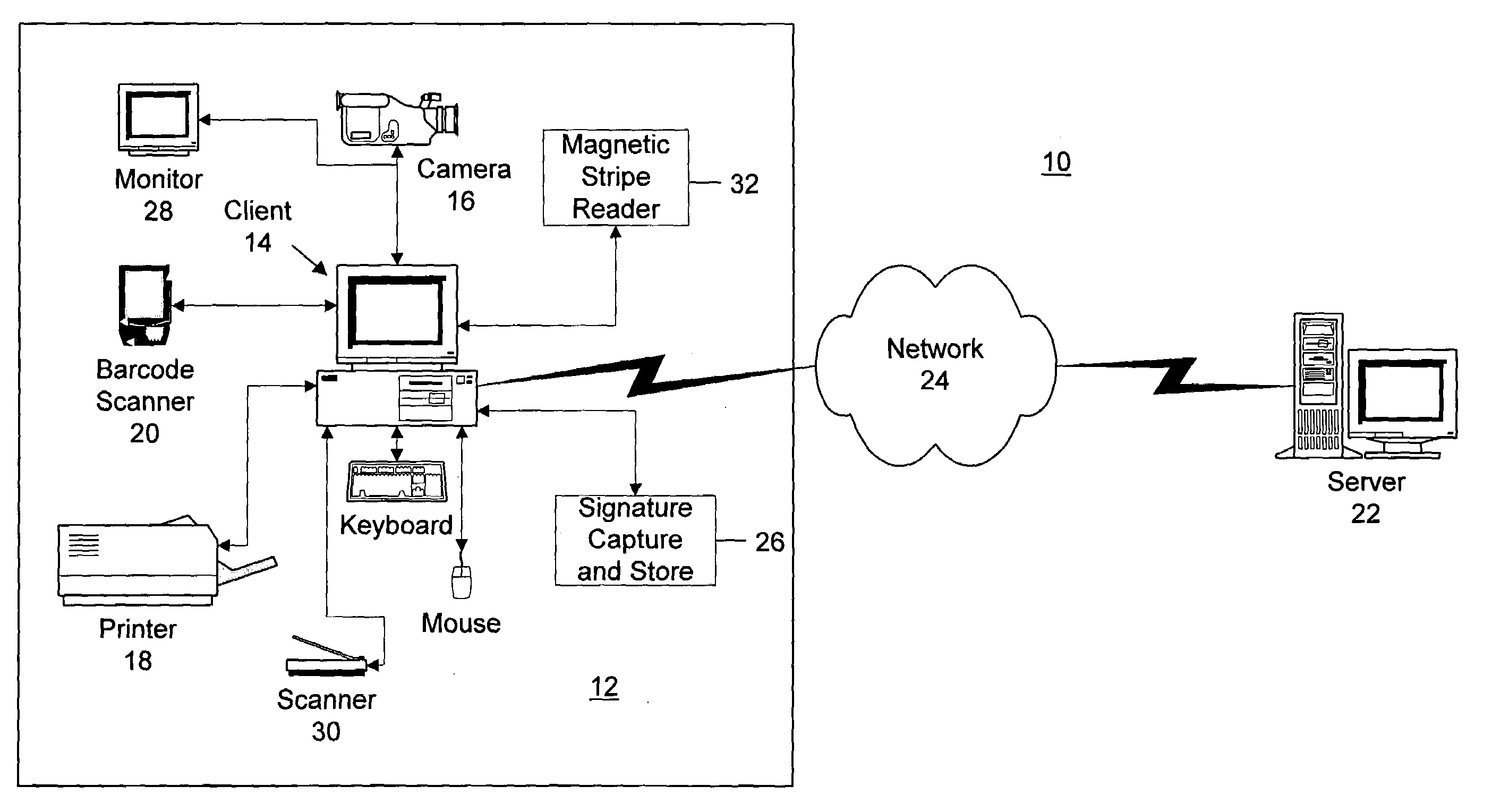
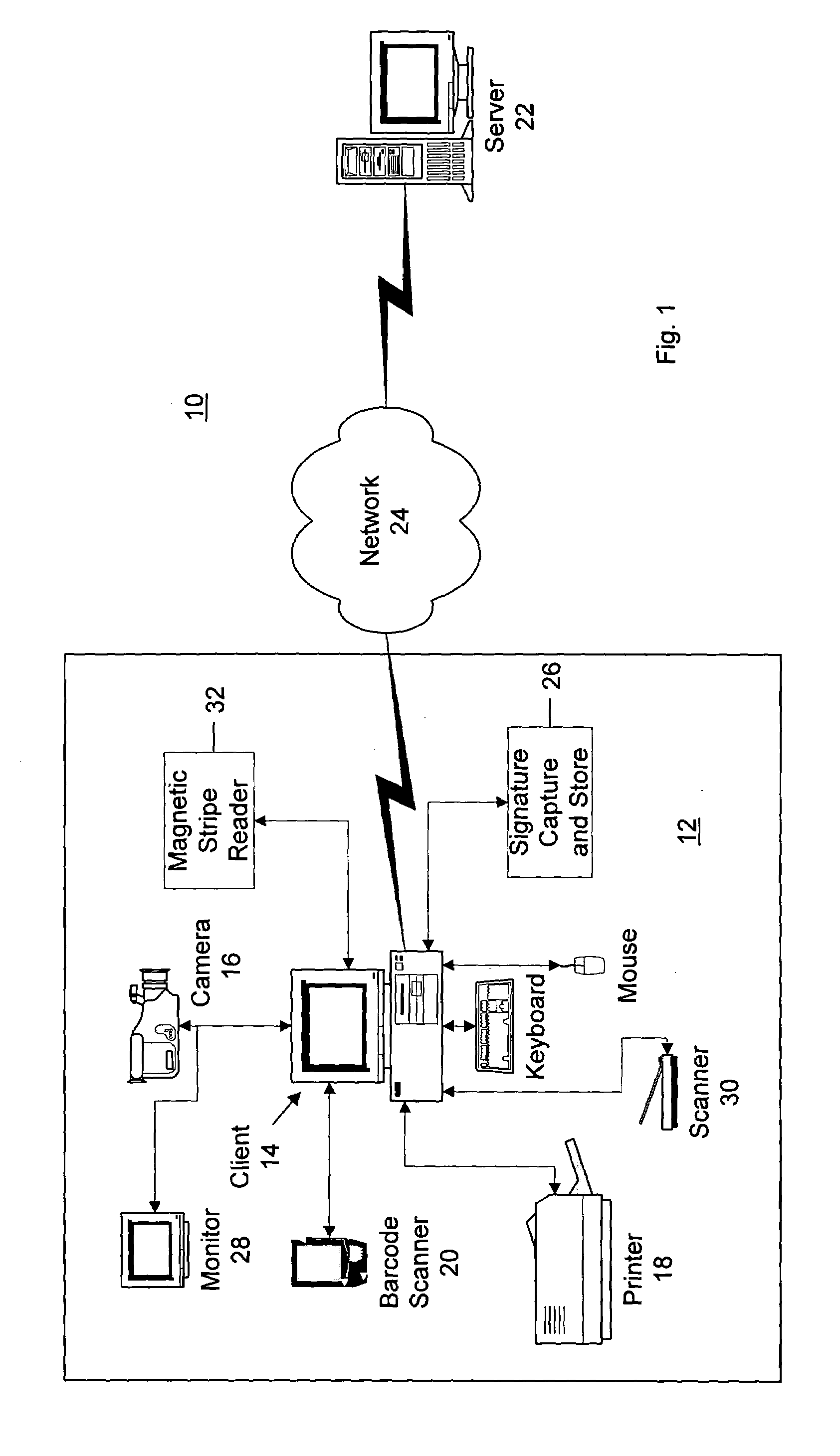
[0008]The invention relates to a system and method for creating a display card such as an identification badge. The system provides a flexible, inexpensive and user-friendly solution for creating photographic identification badges. The system does not require expensive proprietary technology such as specialty printers which require expensive ribbons, or proprietary networking technologies which require extensive training and maintenance. The system smoothly integrates the photograph taking process into the data input process, thus eliminating the need in prior art badge creation systems for separate and inconvenient procedures for taking a visitor's photograph.
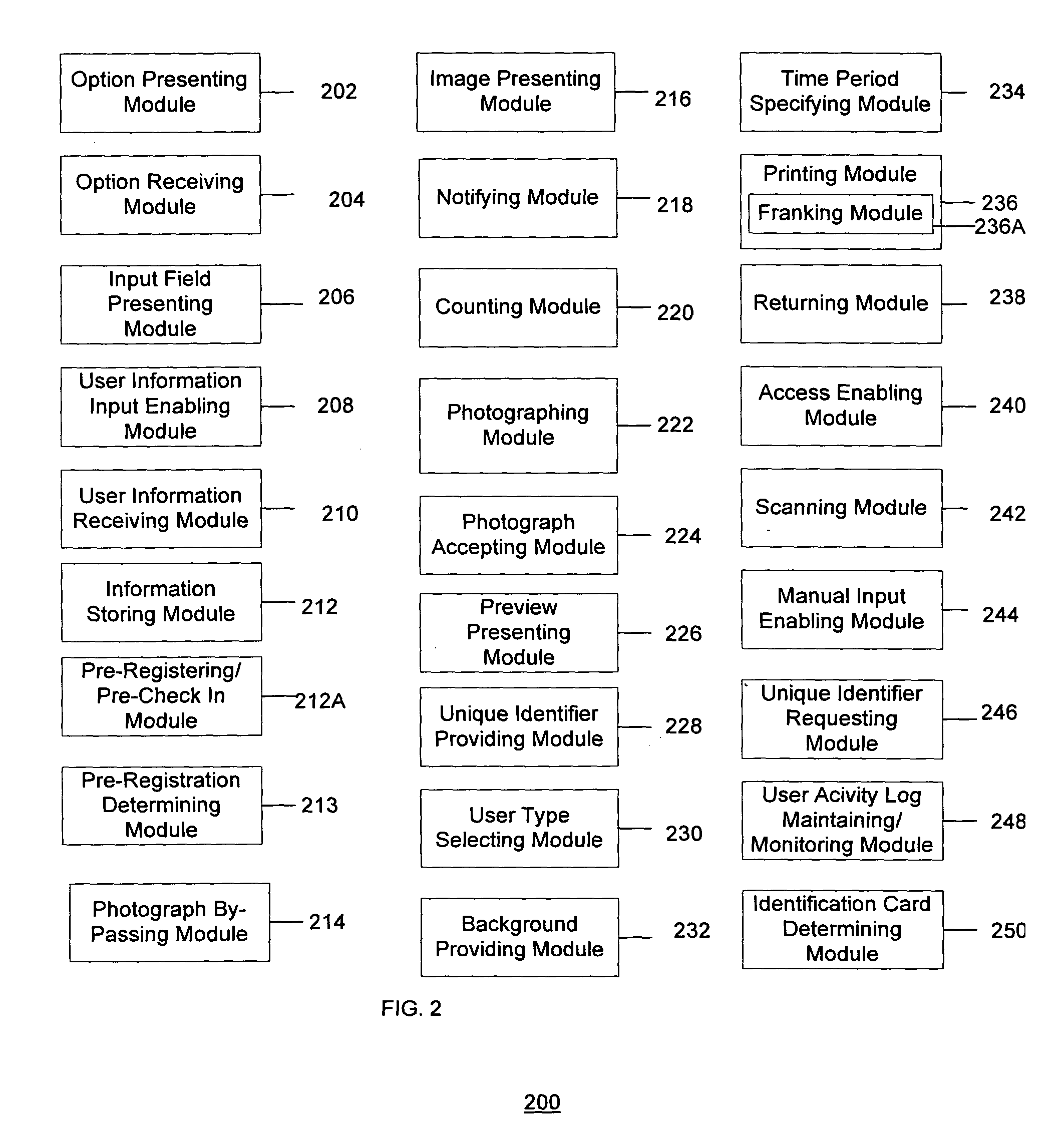
[0010]The identification card is preferably created and printed at the location. The system may include a monitor that presents various displays to the user. The displays may vary depending on the user and a step of the method that the user is attempting to complete. An initial display may present an option to the user that enables the user to create an identification card. After a user selects the option, the user may be presented with one or more input fields for inputting user information. The input fields may be based on a dynamic or static template that may be stored at a client device and / or on a server. The dynamic templates may be used to present a user with a predetermined sequence of displays and / or input fields. The dynamic templates help to ensure that the user is required to input as much information as the host requires, but no more information than is required, thus saving time and making the system more hospitable. A preview of the identification card may be presented along with the input fields. Therefore, as the user inputs the user information, the information may be displayed in the preview of the identification card showing the user how the information is going to be printed on the identification card. The preview preferably displays the identification card on a print media onto which the identification card is to printed.
[0019]The system may also allow a remote attendant or receptionist to service a number of geographically separate facilities or facility entrances. Using the system, a facility could eliminate the need for an attendant or security guard to by physically present at the particular facility entrance. Each lobby supported could be provided with one self-service kiosk, with a remote attendant available by video and / or audio connection to monitor the badge creation process, provide assistance as necessary to the visitor in the badge creation process, and call the person visited to advise her that her visitor has arrived and has been badged and checked in, and is ready to be allowed into the facility and escorted.

Problems solved by technology

One drawback of known methods for issuing an identification card is that the identification card may not be immediately available.
Therefore, the user may have to wait up to several days or more to receive the identification card.
The temporary pass, however, may not include a photograph of the user.
Therefore, because the user may be required to use a temporary pass for a period of time, the user may be using a less secure identification card which may be lost or stolen and used by an unauthorized user.
Another drawback with existing systems is that a photograph of a user may not provide an accurate depiction of the user.
However, present systems have various drawbacks.
Enabling the user to specify where cardholder information and a picture are to be printed on the card results in various card configurations that are more time consuming to read because information is not located in a designated position.
This is troublesome for users that may not have an identification card that may be used.

Method used


Image

  • System and method for creating a display card
  • System and method for creating a display card
  • System and method for creating a display card

Examples


Embodiment Construction

[0032]According to one embodiment, the invention relates to a system and method for creating and printing a display card. According to one embodiment, the display card may be an identification card that is printed and used for identifying a user at a location and / or monitoring access to the location. The display card may be any type of information conveying mechanism. The display card may be, for example, a name badge that has only a user's name printed thereon, a high-level security identification card that includes a photograph and other user information and identifiers that enables access to one or more secure locations, or any variation thereof. The display card may be associated with a particular event. For example, the display card may include text and / or graphics that relate to a specific event. The display card may, for example, have balloons and ice cream cones printed thereon if the display card is to be used at an ice cream social. By way of example, the invention is desc...


PUM


Abstract

A system and method enables a user such as a visitor to a facility to create a photographic identification card for himself. The user terminal prompts a user to enter identifying information including his name, and takes a photograph of the user. An identification badge is printed for the user upon predefined media. The identification card may be provided with a barcode and unique identification number. The user may be presented with a preview of the identification as the identification card is to be printed. Upon exiting the location, the user may scan the barcode or enter the unique identification number to sign out of the system and exit the location. A user activity log may be maintained at a server such that each time an identification card is created, printed or signed out, the log is updated with information regarding the user information, date, time, location or other information.

Description

RELATED APPLICATIONS[0001]This application claims priority from the following U.S. patent applications:[0002]provisional application Ser. No. 60 / 446,817, filed Feb. 11, 2003; provisional application Ser. No. 60 / 411,268, filed Sep. 16, 2002; provisional application Ser. No. 60 / 432,941, filed Dec. 11, 2002; provisional application Ser. No. 60 / 466,689, filed Apr. 30, 2003; and non-provisional patent application Ser. No. 10 / 641,132, filed Aug. 14, 2003. The entire contents of all of these applications are incorporated by reference.FIELD OF THE INVENTION[0003]The invention relates to a system and method for creating a display card. The display card may be used as an identification badge to gain access and / or identify a user, company, or other entity at a location.BACKGROUND OF THE INVENTION[0004]Recently, security concerns have increased dramatically. After the events of Sep. 11, 2001, a renewed awareness for security has been raised. Many countries, governments, businesses, and even ind...

Claims


Application Information

Patent Timeline
Patent Type & Authority Patents(United States)
IPC IPC(8): G06K5/00G07F17/26
CPCG07F17/26
Inventor OLENICK, MICHAELMILLER, MARYMEDRANO, DEBORAHBRATTER, ADAM
Owner CCL LABEL INC
Learn More