Method to decouple assess point association from directional antennas

a technology of directional antennas and assess points, applied in the field of wireless local area network (wlan) technology, can solve the problems of limited wireless connection concurrentness, increased demands, and inability to expand, and achieve the effects of reducing packet collisions, reducing network throughput, and increasing versatility of operation

Inactive Publication Date: 2007-01-30
CISCO TECH INC
View PDF11 Cites 33 Cited by
  • Summary
  • Abstract
  • Description
  • Claims
  • Application Information

AI Technical Summary

Benefits of technology

[0012]There is also a need for WLAN that reduces packet collisions from new unassociated clients.

Problems solved by technology

This scheme does not allow for much expansion as performance demands increase.
This results in a limitation on the number of concurrent wireless connections that can be supported by the cells of the WLAN.
Consequently, some cells must be held off while communication occurs in other cells, thereby reducing data throughput and other network efficiency factors.
However, the number of access points must necessarily be increased to cover the same service area, thereby increasing network overhead.
While SDMA using directional antennas increases throughput, certain difficulties are encountered for clients and access points seeking to associate with each other as mobile clients move from one cell to another.
However, this established method does not extend to an SDMA system employing adaptive directional antennas.
In a WLAN that employs adaptive antennas, there is a risk that a client will not be “seen” by the antennas when the client moves into a new cell or first comes alive.
However, such operation would require that data transfer be halted to associated clients.
However, this would either also subtract access time or create interference for associated clients.
WLANs, particularly those that use omnidirectional antennas, encounter difficulties resulting from the “hidden node” problem.
In this situation, two clients may be separated by a great distance and not aware of each other.
This results in “packet collisions” where data packets over the same channel interfere, resulting in “drop outs” and other data loss.
The problem can still arise if an unassociated client enters the cell and transmits on that channel, resulting in more packet collisions and interference.
This backoff time resulting from packet collisions is a further source of inefficiency.

Method used


Image

  • Method to decouple assess point association from directional antennas
  • Method to decouple assess point association from directional antennas
  • Method to decouple assess point association from directional antennas

Examples


Embodiment Construction

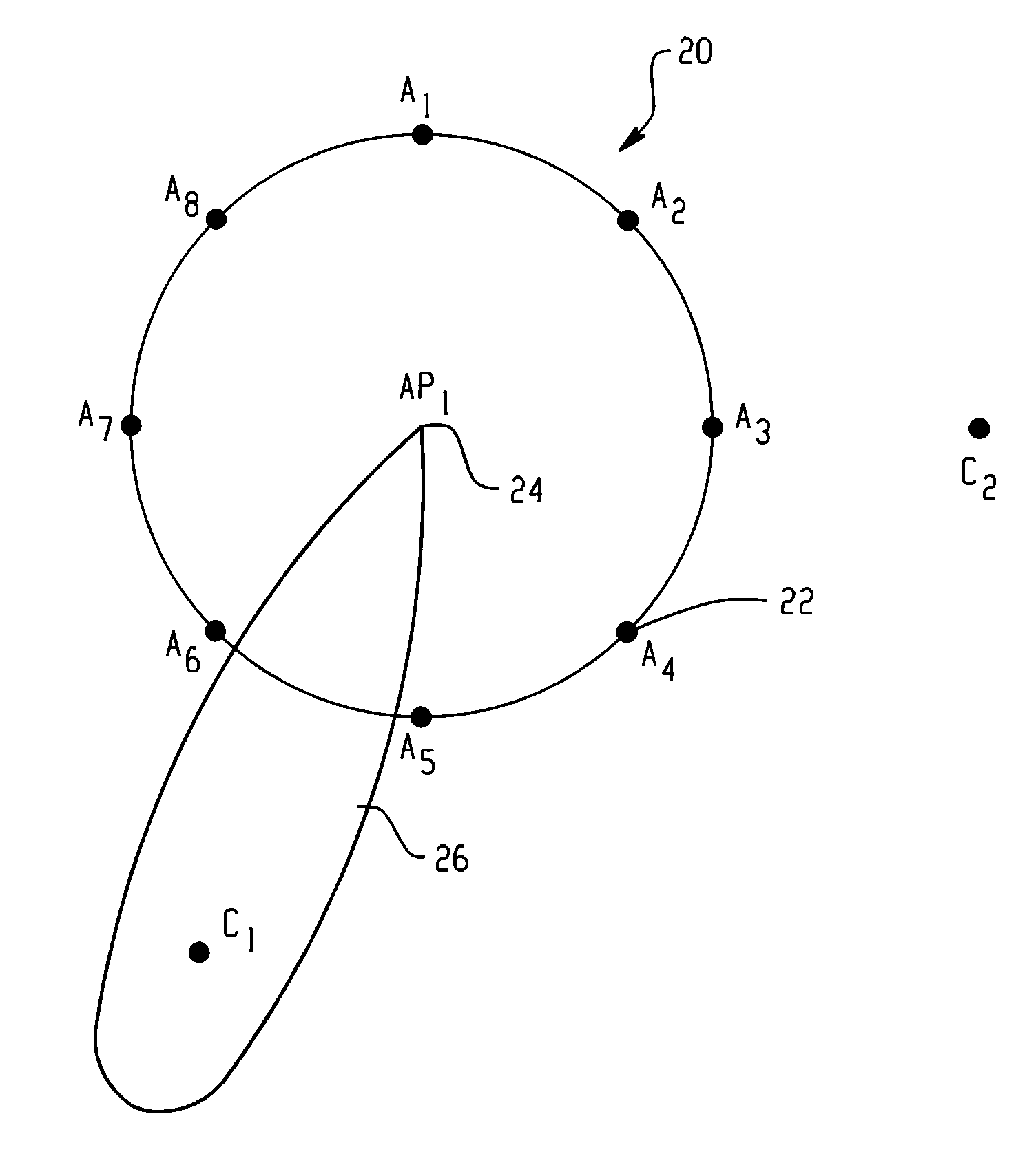
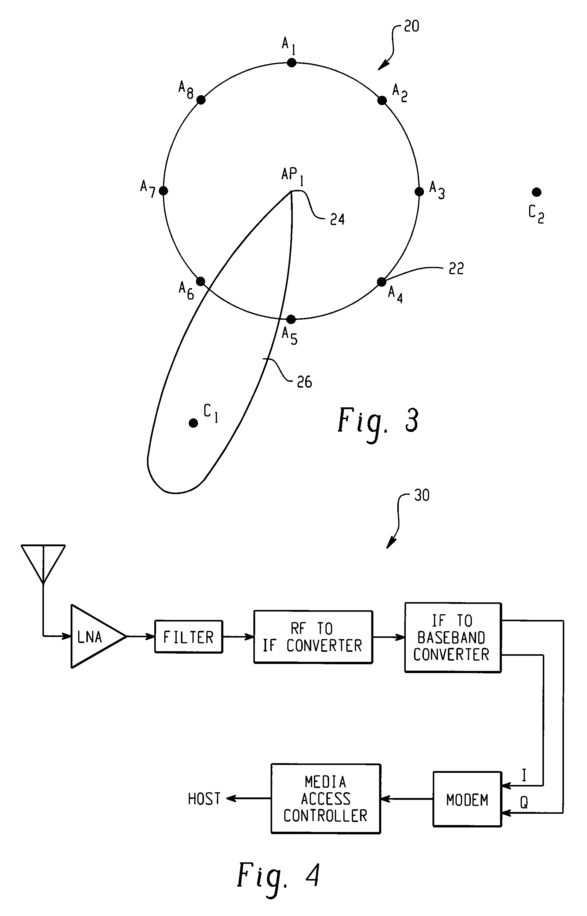
[0021]Improved results over previous-type WLAN schemes are obtained with the method and implementation of network communication in accordance with the present invention. One or more network access points 24, are provided for communicating with a plurality of clients over a number of channels, where each channel includes a plurality of carrier frequency bands. As a special feature of the invention, the access point 24 is equipped with the capability for monitoring one or more dedicated carrier frequency bands for new clients seeking to associate with the network. A new client entering the cell or coming alive within the cell preferably detects a beacon signal from the access point 24 over the dedicated carrier band and sends a response to the access point 24 requesting association. Alternatively, the client may send an association request directly to the access point 24 upon activating within the cell. In either case, the dedicated carrier is monitored and new clients are detected ov...


PUM


Abstract

A method and implementation for network communication is disclosed where one or more network access points are provided for communicating with a plurality of clients over a plurality of carriers. An arrangement is provided for monitoring on or more dedicated carriers for new clients seeking to associate with the network. The new client is detected over the carrier or carriers and he new client is then associated to the network over the carrier or carriers.

Description

BACKGROUND OF THE INVENTION[0001]The present invention is directed to the field of wireless local area network (WLAN) technology, particularly for associating new clients to high-throughput WLANs. Higher data rates have been obtainable for WLANs, particularly under the new IEEE 802.11a standard. This has enabled customers to deploy WLANs in order to exploit the benefits of a wireless network, namely mobile network access and reducing the infrastructure costs of hard-wiring buildings, as with a traditional LAN. At present, data rates of 11 Mbps are found to be adequate. As future WLAN deployments become popular with customers, the performance demands will increase.[0002]In a typical WLAN, an access point is in wireless communication with a plurality of mobile clients, who access the WLAN through the access point. The access point broadcasts and transmits with spatially-separated clients using an omnidirectional antenna, that communicates in a 360 degree field around the access point....

Claims


Application Information

Patent Timeline
Patent Type & Authority Patents(United States)
IPC IPC(8): H04Q7/00H04W16/28
CPCH04W16/28
Inventor CISAR, JAMES M.DOLLARD, MICHAEL S.
Owner CISCO TECH INC
Why Eureka
Try Eureka