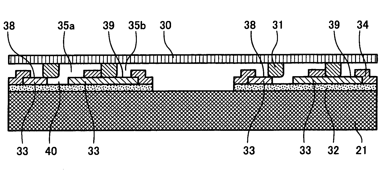
Semiconductor wafer and testing method therefor
a technology of semiconductor wafers and test methods, applied in the direction of individual semiconductor device testing, instruments, basic electric elements, etc., can solve the problems of plastic deformation of probes of probe cards, damage to non-conductor layers, and damage to circuit elements, and achieve high efficiency
- Summary
- Abstract
- Description
- Claims
- Application Information
AI Technical Summary
Benefits of technology
Problems solved by technology
Method used
Image
Examples
first embodiment
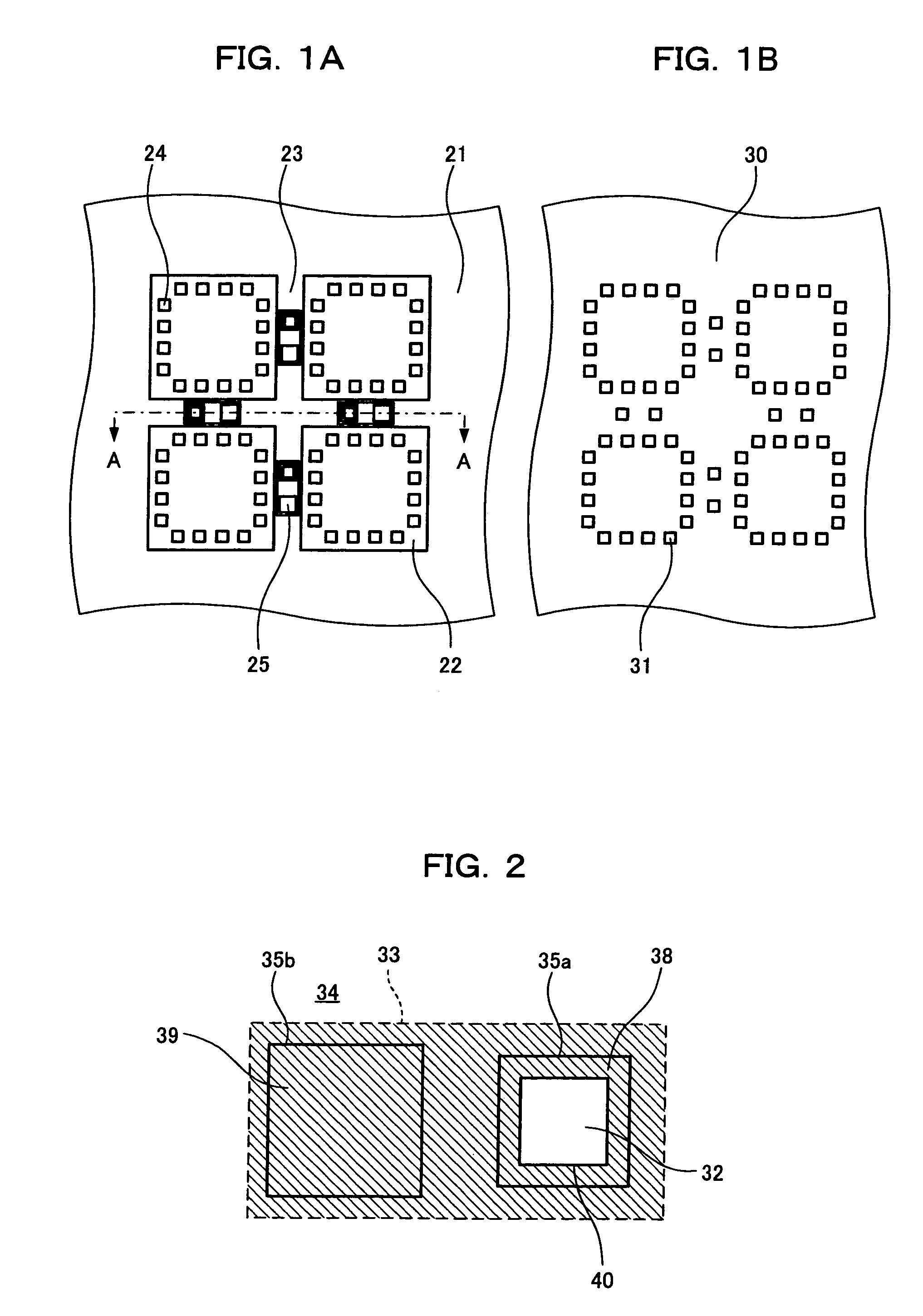
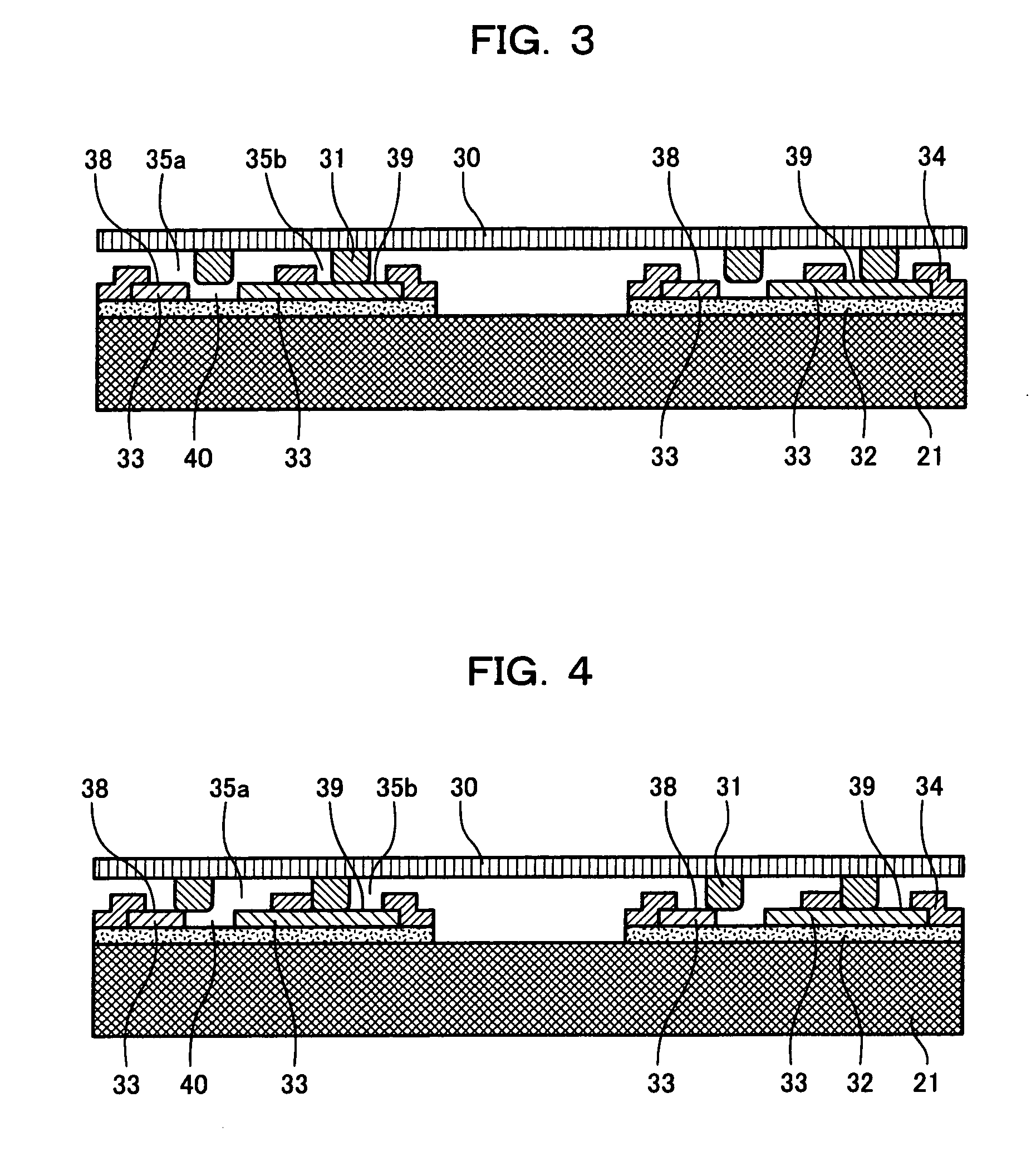
[0080]FIG. 1A is a plan view of a semiconductor wafer according to a first embodiment of the present invention; FIG. 1B is a plan view of a contactor for testing semiconductor devices on the wafer.
[0081]The semiconductor wafer 21 in FIG. 1A includes a number of semiconductor devices 22, scribe lines 23 for scribes formed between the semiconductors 22, and alignment patterns 25 formed inside the scribe lines 23. Electrode terminals 24 for connecting to the external are formed on each semiconductor device 22.
[0082]The alignment pattern 25 is used in a burn-in test or an electrical property test on the semiconductor wafer 21. In the first embodiment, more than one alignment pattern 25 is formed in each of the scribe lines 23 intersecting at right angles.
[0083]The contactor 30 in FIG. 1B is a testing tool for conducting burn-in tests or electrical property tests on the semiconductor wafer 21. The contactor 30 has on a substrate a number of bump electrodes 31 for testing some or all of t...
second embodiment
[0102]A second embodiment of the present invention will be described below. FIG. 6 is a plan view of an alignment pattern 25 and FIG. 7 is a cross-sectional view in direction of arrow B—B of FIG. 6.
[0103]The alignment pattern 25 in FIGS. 6 and 7 includes a rectangular conductor electrode terminal 39 formed by a conducting layer on an underlying insulating layer 32, and a detector electrode terminal 38 surrounding the conductor electrode terminal 39, except along one side of the conductor electrode terminal 39. A gap is provided between the conductor electrode terminal 39 and the detector electrode terminal 38. The gap may be filled with an insulator film such as SiN.
[0104]An upper insulating layer 34 formed over the underlying insulating layer 32 and the conducting layer 33 has a rectangular opening 35 above the detector electrode terminal 38 and the conductor electrode terminal 39. The entire conductor electrode terminal 39 is exposed in the opening 35 and the detector electrode te...
third embodiment
[0110]A third embodiment of the present invention will be described below. FIG. 9 is a plan view of an alignment pattern 25. The alignment pattern 25 in FIG. 9 includes a rectangular conductor electrode terminal 39 formed by a conducting layer on an underlying insulating layer 32, and a detector electrode terminal 38 opposed to and separated by a gap from one end of he conductor electrode terminal 39.
[0111]An upper insulating layer 34 provided over the underlying insulating layer 32 and the conducing layer 33 has an opening 35 above the detector electrode terminal 38 and the conductor electrode terminal 39. In the opening 35, a portion of the conductor electrode terminal 39 and a portion of the detector electrode terminal 38 are exposed from one of the sides of the perimeter of the opening 35, the portion of the detector electrode terminal 38 is exposed along one of the sides of the perimeter of the opening 35, and the underlying insulating layer 32 is exposed in the regions where n...
PUM
 Abstract
Description
Claims
Application Information
 - R&D
- Intellectual Property
- Life Sciences
- Materials
- Tech Scout
- Unparalleled Data Quality
- Higher Quality Content
- 60% Fewer Hallucinations
Browse by: Latest US Patents, China's latest patents, Technical Efficacy Thesaurus, Application Domain, Technology Topic, Popular Technical Reports.
© 2025 PatSnap. All rights reserved.Legal|Privacy policy|Modern Slavery Act Transparency Statement|Sitemap|About US| Contact US: help@patsnap.com


