
Methods of reducing sag in non-aqueous fluids

a non-aqueous fluid and sag reduction technology, applied in the field of particle-containing fluids, can solve the problems of excessive circulation density, sag can occur, and the drilling efficiency to decrease, so as to reduce sag, reduce sag, and increase the viscosity of the fluid composition

Inactive Publication Date: 2007-01-30
CHEVRON PHILLIPS CHEMICAL CO LP
View PDF16 Cites 5 Cited by
  • Summary
  • Abstract
  • Description
  • Claims
  • Application Information

AI Technical Summary

Benefits of technology

The cystol ester compounds effectively reduce sag by up to 100% in drilling fluids, maintaining low viscosity and ensuring efficient fluid circulation and particle suspension, even under dynamic conditions, without adverse effects on flow properties.

Problems solved by technology

Unfortunately, the solid particles, particularly the relatively heavy particles of a weighting agent, may settle and / or stratify in the fluid as it is being pumped through the wellbore.
As a result of such settling, a problem known as sag can occur in which the specific gravity of the drilling fluid along the fluid column varies.
However, those materials undesirably increase the viscosity of the drilling fluid and thus cause the drilling efficiency to decrease.
Further, it may be difficult to remove drill cuttings from the wellbore, resulting in the fluid having an excessive circulation density and thus leading to the loss of its circulation in the wellbore.

Method used


Image

  • Methods of reducing sag in non-aqueous fluids
  • Methods of reducing sag in non-aqueous fluids
  • Methods of reducing sag in non-aqueous fluids

Examples


example 1

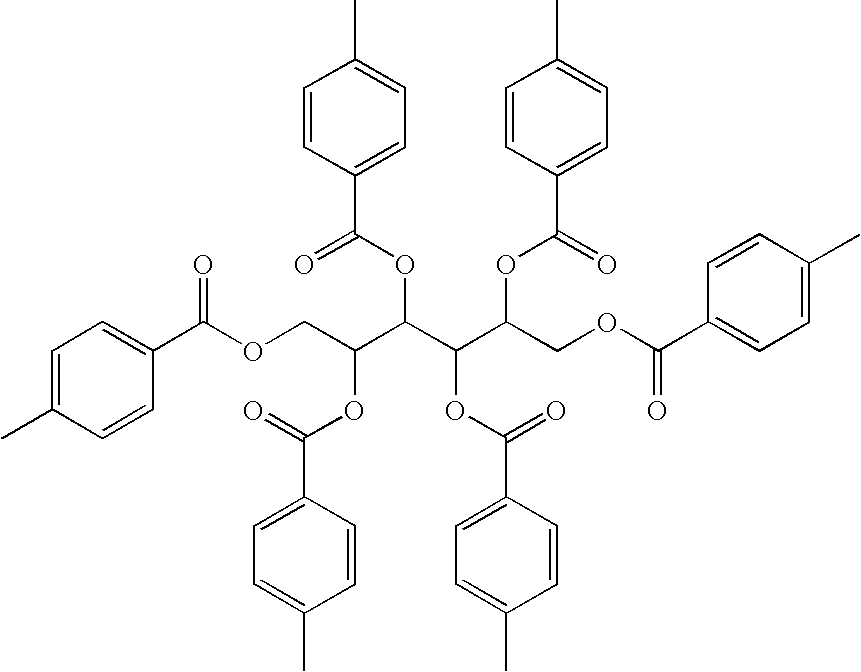
[0024]A sample of hexa-O-para-toluoyl cystol was prepared in accordance with the following procedure. First, 15 g (82.4 mmol) of cystol was added to 84 mL of pyridine, which served as a catalyst as well as the solvent, and stirred to form a suspension. While continuously stirring the suspension, 45.20 mL (494 mmol) of p-toluoyl chloride was added drop-wisely to the suspension for a period of 15 minutes. The resultant light yellow solution was refluxed at 90° C. for 1 hour. The reaction was then quenched with ground ice chips (50 g), and the reaction product was washed twice with 200 mL of an aqueous solution containing 44 wt.% hydrochloric acid (HCl) per total weight of the solution, and then twice with 200 mL of distilled water to remove the pyridine. The cystol ester compound was then extracted from the reaction product by contacting it with 200 mL of dichloromethane, followed by evaporation of the dichloromethane and drying of the resultant cystol ester compound under vacuum. The...

example 2

[0026]A sample of hexa-O-benzoyl cystol was prepared in accordance with the procedure described in Example 1 except that the amount of pridine used was 100 mL and the p-toluoyl chloride was replayed with 58 ml of benzoyl chloride. The hexa-O-benzoyl cystol is represented by the following formula:

[0027]

example 3

[0028]A sample of hexa-O-para-tert-butylbenzoyl cystol was prepared in accordance with the procedure described in Example 1 except that the amount of pyridine used was 100 mL and the p-toluoyl chloride was replaced with 90 mL of p-t-benzoyl chloride. The hexa-O-para-tert-butylbenzoyl cystol is represented by the following formula:

[0029]


PUM

PropertyMeasurementUnit
densityaaaaaaaaaa
heightaaaaaaaaaa
diameteraaaaaaaaaa

Abstract

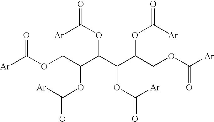
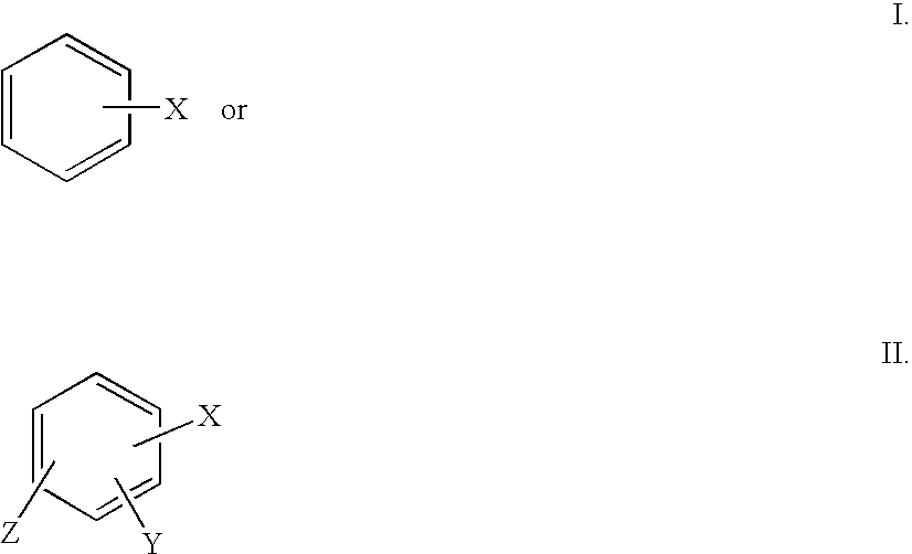
Methods of reducing sag include combining a cystol ester compound with a non-aqueous fluid and particles to reduce sag in the resulting fluid composition without significantly increasing the viscosity of the fluid composition. The fluid composition CONTAINS the non-aqueous fluid, the particles, and the cystol ester compound. Suitable cystol ester compounds include cystol ester and derivatives of cystol ester having mono-, di-, or tri-substituted aromatic compounds as substituents. The non-aqueous fluid may CONTAINS an invert emulsion, diesel oil, mineral oil, an olefin, an organic ester, a synthetic fluid, or combinations thereof. Further, the fluid composition may be used as a wellbore servicing fluid such as a drilling fluid. The particles may CONTAINS a weighting agent, e.g., barite, galena, hematite, dolomite, calcite, or combinations thereof. The fluid composition may also include organophilic clay.

Description

CROSS-REFERENCE TO RELATED APPLICATIONS[0001]Not applicable.STATEMENT REGARDING FEDERALLY SPONSORED RESEARCH OR DEVELOPMENT[0002]Not applicable.REFERENCE TO A MICROFICHE APPENDIX[0003]Not applicable.FIELD OF THE INVENTION[0004]The present invention relates to particle-containing fluids, and more particularly to methods of reducing sag in non-aqueous fluids, e.g., invert emulsions, containing particles by combining cystol ester and / or at least one of its derivatives with the fluids.BACKGROUND OF THE INVENTION[0005]Subterranean deposits of natural resources such as gas, water, and crude oil are commonly recovered by drilling wellbores to tap subterranean formations or zones containing such deposits. A drilling fluid or mud is usually circulated through a wellbore as it is being drilled to cool the bit, keep the deposits confined to their respective formations during the drilling process, and return drill cuttings, i.e., small pieces of shale and / or rock generated by the drill bit, bac...

Claims


Application Information

Patent Timeline
Patent Type & Authority Patents(United States)
IPC IPC(8): E21B33/00C09K8/32
CPCC09K8/32C09K8/02C09K8/035C09K8/36
Inventor FALANA, OLUSEGUN M.PATEL, BHARAT B.STEWART, WAYNE S.
Owner CHEVRON PHILLIPS CHEMICAL CO LP
Learn More