
Self-locking seal ring

Inactive Publication Date: 2007-01-23
CAMACHO LUIS A
View PDF5 Cites 26 Cited by
  • Summary
  • Abstract
  • Description
  • Claims
  • Application Information

AI Technical Summary

Benefits of technology

[0013]The present invention is directed to a self-locking seal ring which is suitable for sealing butterfly valves in aircraft, aerospace and other applications; is easy to install in a ring groove in a main butterfly plate of a butterfly valve; and facilitates optimum sealing of the main butterfly plate with respect to the butterfly valve housing.
[0014]An object of the present invention is to provide a self-locking seal ring which facilitates an effective seal between a main butterfly plate and a valve body of a butterfly valve.
[0015]Another object of the present invention is to provide a self-locking seal ring that may be used in a variety of industries, including but not limited to the aircraft and aerospace industries, to effectively seal a main butterfly plate with respect to a valve body of a butterfly valve.
[0017]Yet another object of the present invention is to provide a self-locking seal ring which can be used with a second inner ring to form a seal ring set that effectively controls leakage in a butterfly valve.
[0019]Yet another object of the present invention is to provide a self-locking seal ring which contributes to operational longevity of a butterfly valve.
[0020]A still further object of the present invention is to provide a self-locking seal ring which is easy to install in and remove from a butterfly valve to expedite and simplify maintenance of the butterfly valve.

Problems solved by technology

In the aircraft industry, seal rings are frequently used in butterfly valves that are typically not very reliable due to the nature of the environment in which they must operate.
This assembly process is time-consuming and increases the labor hours during valve overhaul.
If a valve fails, depending on its location, it can render the bleed system and its accessories inoperative.
Since the typical system has high pressure on one side and low pressure on the opposite side of the plate, if the ring ends are not secured to the plate or if the ring has a “self-locking” mechanism, pressure can cause the ring to “blow-out” of the groove.
This method, while effective in securing the ring, results in high leakage across the seal / plate assembly.
Most of the time, the rings have straight cut joints which are not optimally effective to control leakage.
As the ring is now locked in place, it starts wearing at both extremes closest to the axis of rotation of the main butterfly plate, thus further increasing leakage across the plate.
The major disadvantage of the method is looseness of the press fit of the pin.
If the pin is lost, it can travel downstream of the valve, causing damage to other components of the system or to the valve itself.
As with the staple, this method also causes the ring to wear at the areas closest to the axis of rotation of the butterfly plate, thus causing leakage to increase.
Due to the intricate shape of the locking feature of the Kaydon Corp. self-locking ring, the ring cannot be installed inside a normal machined groove.
It has been found that leakage control of the ring is better than previous cases, although the biggest disadvantage of the ring is the special provisions the butterfly plate must have to facilitate its installation.
Assembly procedures become cumbersome, time-consuming and expensive.
However, a common drawback of the seal ring is the difficult installation of the ring into the ring groove in a butterfly valve housing.

Method used


Image

  • Self-locking seal ring
  • Self-locking seal ring
  • Self-locking seal ring

Examples


Embodiment Construction

[0032]Shown throughout the drawings, the present invention is generally directed towards a self-locking seal ring which is suitable for sealing butterfly valves in aircraft, aerospace and other applications; is easy to install in a ring groove in a main butterfly plate of a butterfly valve; facilitates optimum sealing of the main butterfly plate with respect to the butterfly valve housing; and facilitates ease in maintenance of a butterfly valve.

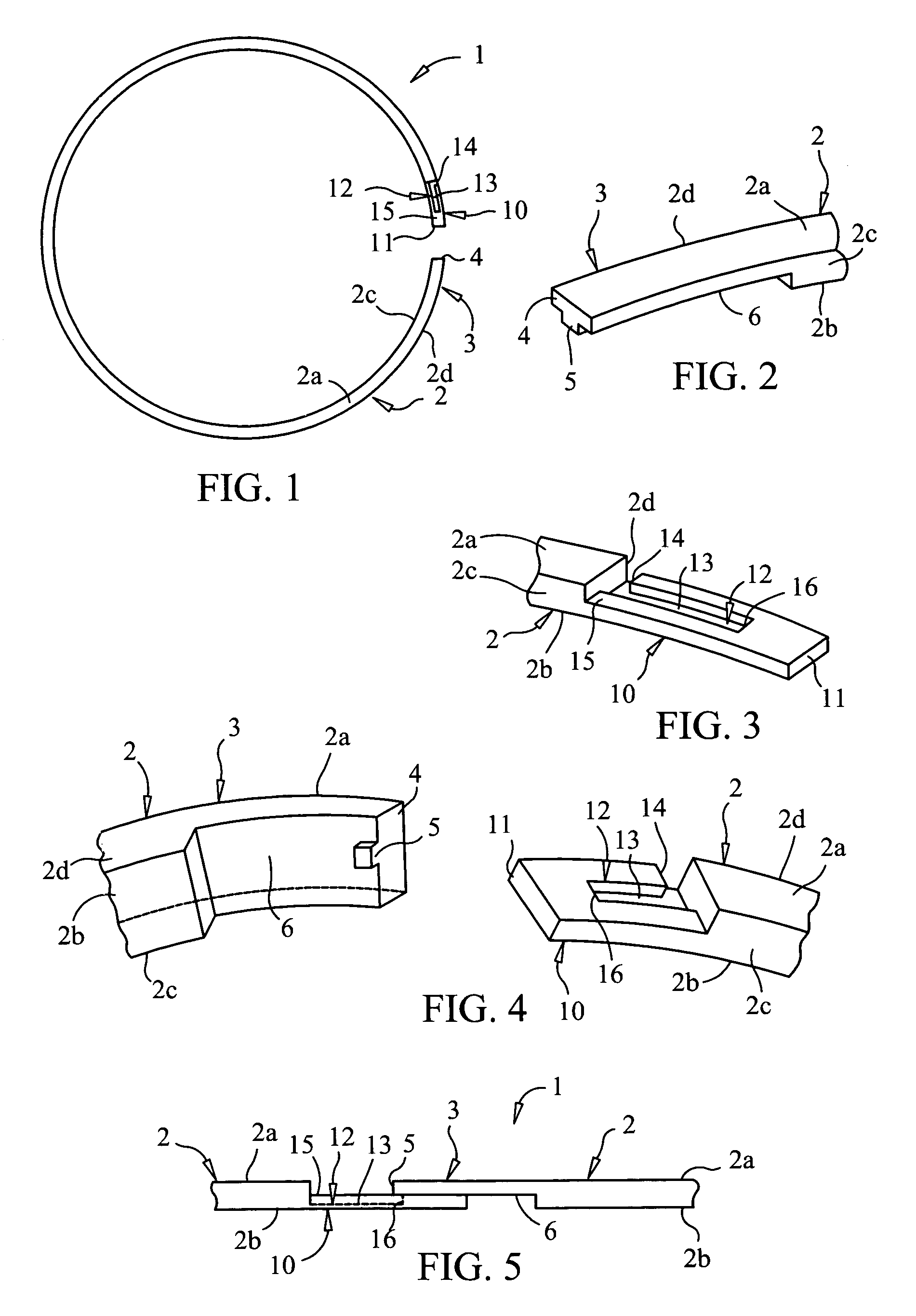
[0033]Initially referring to FIGS. 1–4, an illustrative embodiment of the self-locking seal ring of the present invention is generally indicated by reference numeral 1. The seal ring 1 includes a generally circular ring body 2 which is manufactured from a variety of known materials, most typically steel alloys. For purposes of description herein, the ring body 2 includes an upper surface 2a and a lower surface 2b. However, it will be understood that the upper surface 2a and lower surface 2b of the ring body 2 are simply opposite surfaces of ...


PUM


Abstract

A self-locking seal ring is disclosed. The self-locking seal ring includes a ring body having a tab end segment on one end and a channel end segment on the opposite end. A lock tab is provided on the tab end segment, and a lock channel is provided on the channel end segment for receiving the lock tab. The self-locking seal ring is easy to install in a ring groove in a main butterfly plate of a butterfly valve, for example, and facilitates optimum sealing of the main butterfly plate with respect to the butterfly valve housing.

Description

FIELD OF THE INVENTION[0001]The present invention relates generally to seal rings for sealing butterfly valves particularly in aerospace applications. More particularly, the present invention relates to a novel self-locking seal ring which is easily installed in a ring groove of a butterfly valve and effectively seals the valve to improve leakage control.BACKGROUND OF THE INVENTION[0002]Butterfly valves are extensively used in the bleed air, pneumatic and air conditioning systems of most modern aircraft. In the aircraft industry, seal rings are frequently used in butterfly valves that are typically not very reliable due to the nature of the environment in which they must operate. Most butterfly valve applications demand good leakage control at high and low pressures as well as optimum performance over a large range of operating temperatures.[0003]Butterfly valves typically include a valve housing within which is disposed a rotating main butterfly plate. A seal ring is seated in a se...

Claims


Application Information

Patent Timeline
IPC IPC(8): B60T11/236
CPCB64D13/02F16K1/2261F16J15/3272F16J9/14
Inventor CAMACHO, LUIS A.
Owner CAMACHO LUIS A
Learn More