Optical transmission system and optical transmitter used therein
- Summary
- Abstract
- Description
- Claims
- Application Information
AI Technical Summary
Benefits of technology
Problems solved by technology
Method used
Image


Examples
first embodiment
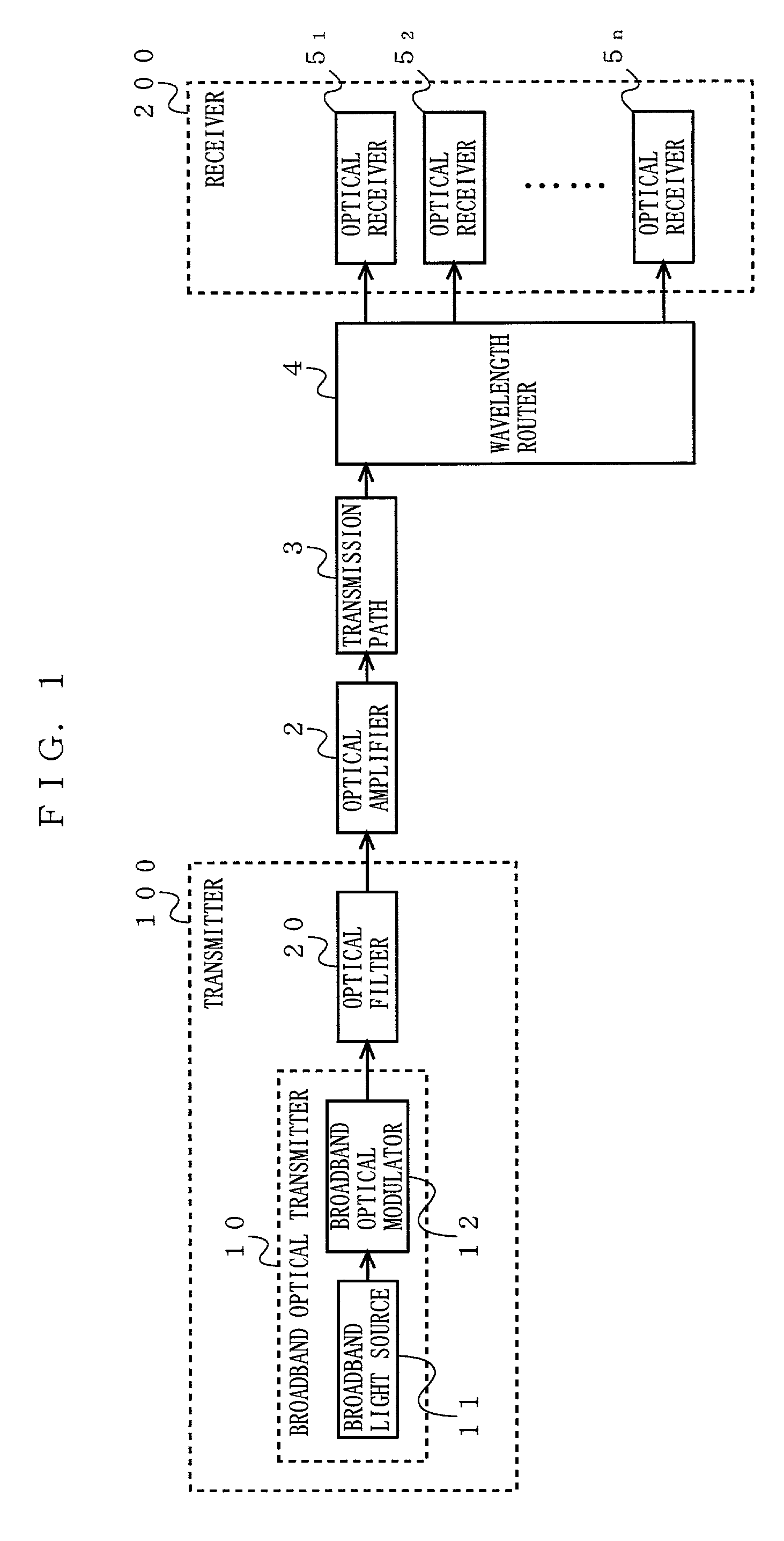
[0065]Referring to FIG. 1, described below is an optical transmission system according to a first embodiment of the present invention. FIG. 1 is a block diagram showing the structure of the optical transmission system. In FIG. 1, the optical transmission system includes a transmitter 100 and a receiver 200 connected with each other via an optical amplifier 2, a transmission path 3, and a wavelength router 4. The transmitter 100 includes a broadband optical transmitter 10, and an optical filter 20. The broadband optical transmitter 10 is provided with a broadband light source 11, and a broadband optical modulator 12. The receiver 200 is provided with n (where n is a natural number) pieces of optical receivers 51 to 5n. Herein, any component block identical to that of the Background Art section is under the same reference numeral.
[0066]In the broadband optical transmitter 10 of the transmitter 100, the broadband light source 11 outputs broadband light to the broadband optical modulato...
second embodiment
[0076]Referring to FIG. 3, described below is an optical transmission system according to a second embodiment of the present invention. FIG. 3 is a block diagram showing the structure of the optical transmission system. In FIG. 3, compared with the optical transmission system of the first embodiment, i.e., specifically with the transmitter 100 thereof, a transmitter 110 further includes a wavelength multiplexing optical transmitter 30 and a coupler 40, and the wavelength bandwidth transmittable by an optical filter 21 therein is different from that by the optical filter 20. There is no other difference therebetween, and any component block identical to that of the first embodiment is provided with the same reference numeral, and not described again.
[0077]In the transmitter 110 of the optical transmission system, the wavelength multiplexing optical transmitter 30 includes a variable wavelength light source 31, and a wavelength multiplexing optical modulator 32. The variable wavelengt...
third embodiment
[0101]Referring to FIG. 6, described next is an optical transmission system according to a third embodiment of the present invention. FIG. 6 is a block diagram showing the structure of the optical transmission system. In FIG. 6, compared with the optical transmission system of the second embodiment, i.e., specifically with the transmitter 110 thereof, a first broadband optical transmitter 70 is provided as an alternative to the broadband optical transmitter 10, and a second broadband optical transmitter 60 and an optical filter 22 are further provided. There is no other difference therebetween, and any component block identical to that of the second embodiment is provided with the same reference numeral, and not described again.
[0102]In the transmitter 120 of the optical transmission system, the first broadband optical transmitter 70 includes a broadband light source 71 and a first broadband optical modulator 72, which are the same as the broadband light source 11 and the broadband ...
PUM
 Abstract
Description
Claims
Application Information
 - R&D Engineer
- R&D Manager
- IP Professional
- Industry Leading Data Capabilities
- Powerful AI technology
- Patent DNA Extraction
Browse by: Latest US Patents, China's latest patents, Technical Efficacy Thesaurus, Application Domain, Technology Topic.
© 2024 PatSnap. All rights reserved.Legal|Privacy policy|Modern Slavery Act Transparency Statement|Sitemap