
Belt type continuously variable transmission

a technology of continuously variable transmission and belt, which is applied in the direction of gearing, mechanical equipment, hoisting equipment, etc., can solve the problems of uneven abrasion of the surface (v face) chipping or abnormal abrasive wear of the v face, and impairing the durability of the v bel

Active Publication Date: 2007-01-16
HONDA MOTOR CO LTD
View PDF3 Cites 7 Cited by
  • Summary
  • Abstract
  • Description
  • Claims
  • Application Information

AI Technical Summary

Benefits of technology

[0008]The present invention is to solve these problems. It is an object of the present invention to provide a belt type continuously variable transmission that can maintain optimal contact condition between the V faces of the drive and driven pulleys and the V belt which are formed with a convex arc.
[0011]By the above described arrangement, the drive and driven pulleys and the V belt are always kept in optimal contact condition to achieve a sufficient range of speed change ratio. As a result, the drive and driven pulleys and the V belt will not experience abnormal abrasion. Because the contact surfaces are formed simply as an arc, the production of these components are relatively easy.
[0013]In this way, a restraint is provided against the Hertz stress at the point in contact between the drive and driven pulleys and the V belt, which stress can otherwise become excessive. This is advantageous for achieving a good speed change ratio.
[0019]By this arrangement, the V belt is protected against misalignment and thereby against abnormal abrasion and twisting. As a result, the durability of the V belt is improved.

Problems solved by technology

While the V belt is misaligned, uneven abrasion occurs in the surfaces (V faces) of the V belt in contact with the drive and driven pulleys.
Moreover, the above mentioned twisting of the V belt impairs the durability of the V belt.
However, if the curvature of the V faces of the drive and driven pulleys is excessive, the Hertz stress (compressive stress) at the part in contact with the V belt becomes large enough to cause a chipping or an abnormal abrasive wear in the V faces, resulting in a remarkable decrease in durability.
In addition, if the V faces are defined by a complicated mathematical function, then the production of the drive and driven pulleys and the V belt becomes difficult.
Furthermore, if the distance that the points in contact between the V belt and the drive and driven pulleys travel while the speed change ratio is varied is not defined (this distance is hereinafter referred to as “contact lengths”), then optimal contact condition is not achieved.
In this case, a contact can occur at an edge of the V faces of the V belt, and this condition leads to an abnormal abrasion and results in the transmission not achieving a sufficient range of speed change ratio.

Method used


Image

  • Belt type continuously variable transmission
  • Belt type continuously variable transmission
  • Belt type continuously variable transmission

Examples


Embodiment Construction

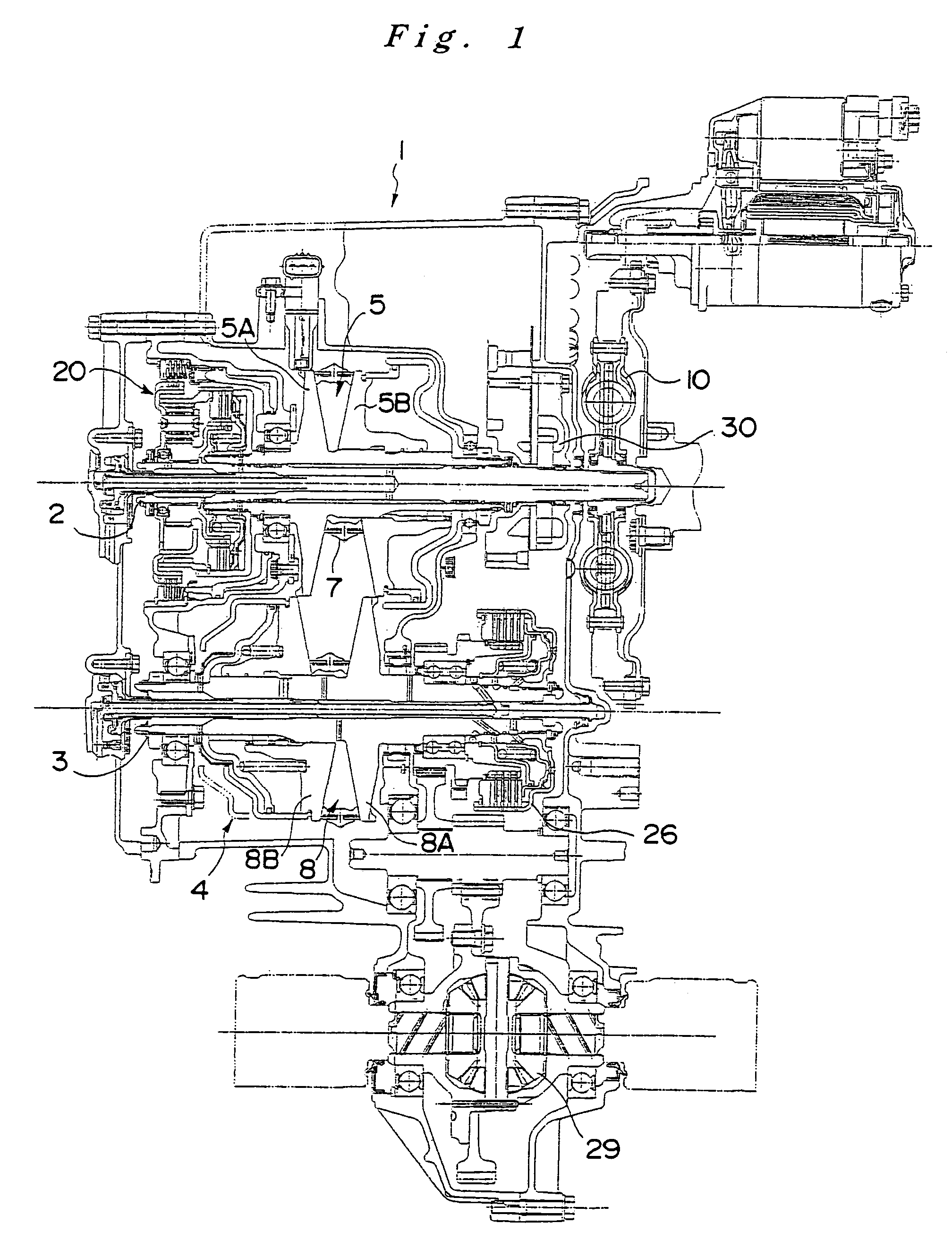
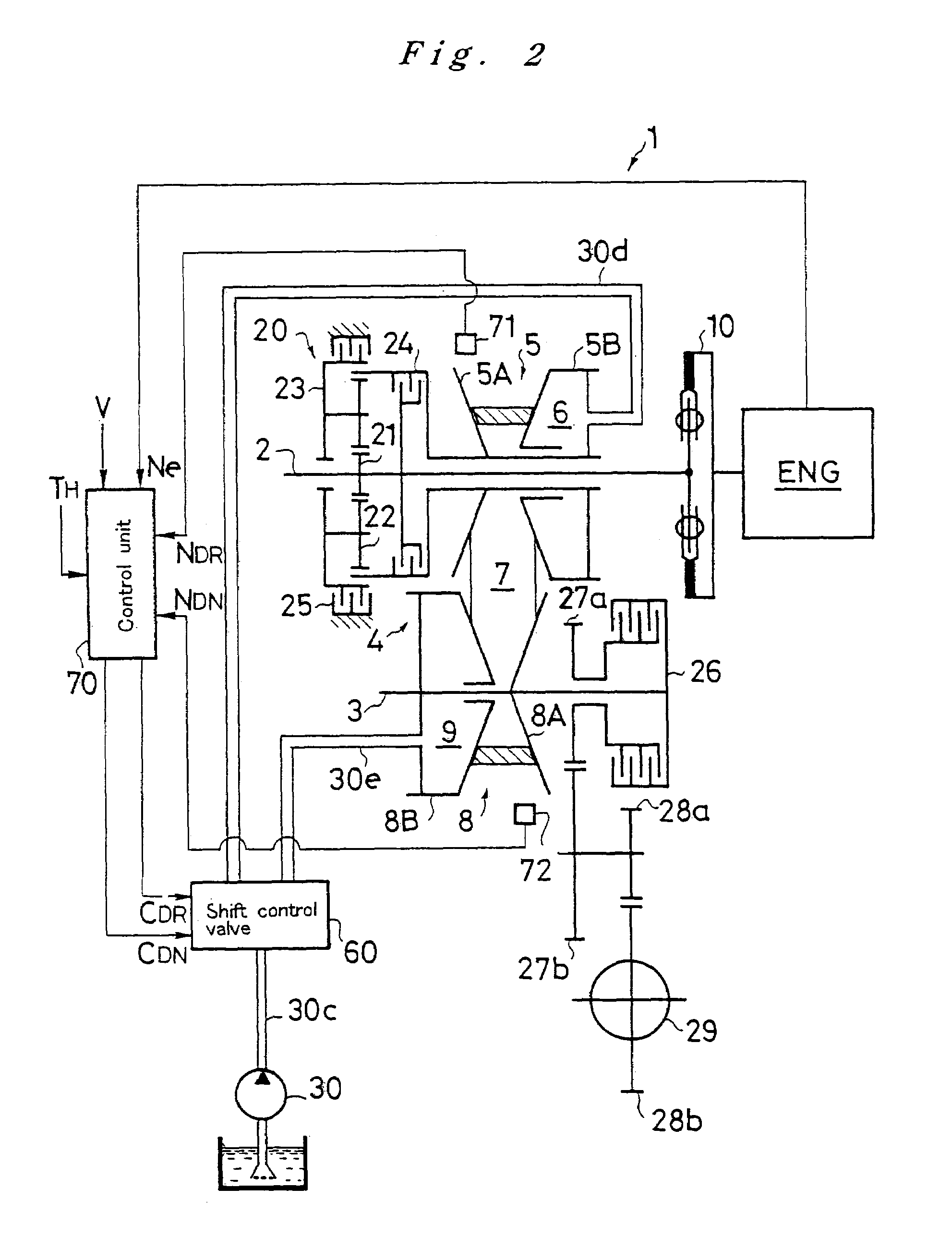
[0031]Now, a preferred embodiment of the present invention is described in reference to the drawings. FIG. 1 and FIG. 2 show a whole view of a belt type continuously variable transmission 1 according to the present invention. The belt type continuously variable transmission (CVD 1 comprises a transmission input shaft 2, a countershaft 3, a metal V belt mechanism 4 and a planetary gear type forward / reverse switching mechanism 20. The input shaft 2 is connected through a flywheel damper 10 to the engine ENG, and the countershaft 3 is disposed in parallel with the input shaft 2. The metal V belt mechanism 4 is disposed around these shafts 2 and 3, and the planetary gear type forward / reverse switching mechanism 20 is placed over the input shaft 2. The belt type continuously variable transmission 1 is equipped with a hydraulic pump 30 and a shift control valve 60 for speed ratio control, and hydraulic oil being supplied from the hydraulic pump 30 through oil passages 30c˜30e to the shift...


PUM


Abstract

In a belt type continuously variable transmission having a variable width drive pulley, a variable width driven pulley, and a metal V belt, which is disposed around the drive and driven pulleys, the contour of the surfaces (V faces) in contact with the metal V belt in the cross-sectional view through the axes of the drive and driven pulleys is an arc that has a first radius of curvature rp and is convex to the metal V belt. The contour of the surfaces (V faces) in contact with these two pulleys in the cross-sectional view perpendicular to the longitudinal direction of the metal V belt is an arc that has a second radius of curvature re and is convex to the drive and driven pulleys.

Description

RELATED APPLICATIONS[0001]This application claims the priority of Japanese Patent Application No. 2003-014413 filed on Jan. 23, 2003, which is incorporated herein by reference.FIELD OF THE INVENTION[0002]The present invention relates generally to a belt type continuously variable transmission that comprises a variable width drive pulley, a variable width driven pulley and a V belt, which is disposed around these pulleys.BACKGROUND OF THE INVENTION[0003]Various such belt type continuously variable transmissions and their control systems have been proposed and put into practical use. A typical belt type continuously variable transmission comprises a drive-pulley actuator, which is used to adjust the width of the drive pulley, and a driven-pulley actuator, which is used to adjust the width of the driven pulley, in axial thrust control. With these actuators, the axial thrusts applied on the drive pulley and the driven pulley are controlled to adjust the widths of the pulleys for control...

Claims


Application Information

Patent Timeline
Patent Type & Authority Patents(United States)
IPC IPC(8): F16H55/56F16H9/16F16G5/16F16H9/18F16H61/662
CPCF16G5/16F16H9/18F16H9/125
Inventor YOSHIDA, HIDEAKI
Owner HONDA MOTOR CO LTD
Learn More