
N-dimensional filter and method for n-dimensionally filtering an original image pixel

a filter and original image technology, applied in the field of n-dimensional filters, can solve the problems of serial arrangement not producing optimal, deterioration of the other, insufficient noise reduction, etc., and achieve the effect of enhancing the sharpness of the original image, reducing noise, and facilitating and reducing costs

Inactive Publication Date: 2007-01-09
DISPLAY INNOVATIONS INC
View PDF6 Cites 8 Cited by
  • Summary
  • Abstract
  • Description
  • Claims
  • Application Information

AI Technical Summary

Benefits of technology

[0019]Starting from the above-noted prior art, it is the object of the invention to provide noise reduction and sharpness enhancement to an original pixel in an easier and cheaper manner.
[0022]Consequently, there is no need for applying a separate sharpness enhancement filter in series with a noise reduction filter. Therefore, the solution can be implemented easily and inexpensively.
[0023]Advantageously, when applying the transmission function to the original pixel, each pixel in the neighborhood of the original pixel contributes either to the noise reduction or to the sharpness enhancement of the original pixel, but not to both.
[0024]According to a preferred embodiment, the transmission function Ff(p) has the advantage that it is very generic due to its recursive character. It enables the use of already filtered pixels for calculating the transmission function Ff(p) for new pixels.
[0026]It is advantageous to filter only a selected spectral component of the input signal by said N-dimensional filter. In this case, the rest of the input signal, which is usually a video signal, is passed by said N-dimensional filter without filtering.

Problems solved by technology

However, for improving the quality of images, very often noise reduction is not enough.
However, spectrally, this serial arrangement does not produce an optimal result.
Hence, there is a conflicting spectral demand on both filters and, generally, the optimization of one leads to deterioration of the other.
However, this also requires some compromise since peaking tends to enhance remaining image noise.

Method used


Image

  • N-dimensional filter and method for n-dimensionally filtering an original image pixel
  • N-dimensional filter and method for n-dimensionally filtering an original image pixel
  • N-dimensional filter and method for n-dimensionally filtering an original image pixel

Examples


Embodiment Construction

[0034]In the following, a preferred embodiment of the present invention will be described by referring to FIGS. 1 and 2.

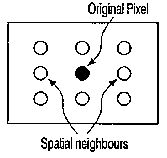
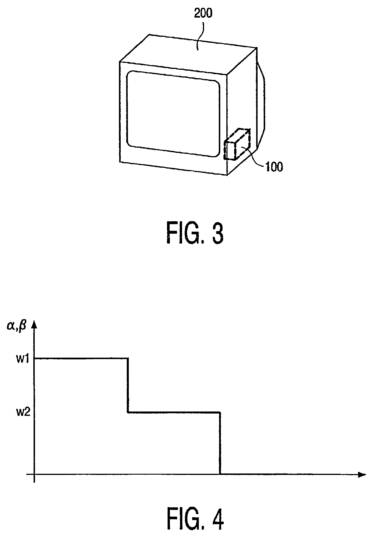
[0035]The invention concerns, preferably but not exclusively, non-linear spatial, recursive spatial or spatial-temporal filters. Consequently, the invention might, e.g., be based on a non-linear recursive spatio-temporal filter having a transmission function Ff(p) as defined in equation 1. Said transmission function defines the filter output for an original image pixel input to said filter. Depending on whether or not one of the constants γ or δ is zero, the transmission function includes a different number of groups α, β of filter coefficients. In general, for defining said filter output, said transmission function carries out a mathematical combination of filter-coefficients α(p, n), β(p, n) which, respectively, belong to groups α and β of filter coefficients, and which are, according to the present invention, defined as follows:

[0036]α⁡(p,n)={w1:Δ⁡(p,n)Th1w2:Th1...


PUM


Abstract

Known N-dimensional filters 100 and methods for N-dimensionally filtering apply noise reduction to an original image pixel. However, carrying out only noise reduction to a pixel of an image is often not enough when a good picture quality is required. Thus, additionally, sharpness enhancement (peaking) is carried out. However, noise reduction and peaking have contrasting spectral behaviors which lead to non-optimal results when both operations, noise reduction and peaking, are implemented in series. By appropriately defining coefficients α(p, n) or β(p, n) of the transmission function, the transmission function is capable of applying both noise reduction and sharpness enhancement to the input signal of the N-dimensional filter 100.

Description

BACKGROUND OF THE INVENTION[0001]1. Field of the Invention[0002]The invention relates to an N-dimensional filter having a transmission function for applying noise reduction to an original image pixel being provided to the N-dimensional filter by a received input-signal, wherein said transmission function comprises at least one filter-coefficient.[0003]The invention further relates to a method for N-dimensionally filtering an original image pixel p according to a transmission function in order to apply noise reduction to said pixel p.[0004]2. Description of the Related Art[0005]Such N-dimensional filters or filtering methods are known in the art, e.g., from European Patent Application No. EP 0 682 841 B1, corresponding to U.S. Pat. Nos. 5,715,335 and 5,742,355, the contents of which is hereby incorporated by reference. In the European patent application, for every pixel position p=(x, y, t)T, where T indicates transposition, in an input luminance signal F(p), the filter transmission ...

Claims


Application Information

Patent Timeline
IPC IPC(8): G06K9/40G06T5/00G06T5/20H04N5/208H04N5/21
CPCG06T5/20H04N5/208H04N5/21G06T5/003G06T5/002G06T2207/20192G06T2207/10016G06T5/73G06T5/70
Inventor OJO, OLUKAYODE ANTHONYKWAAITAAL-SPASSOVA, TATIANA GEORGIEVA
Owner DISPLAY INNOVATIONS INC
Learn More