Microphone array sound source location system with imaging overlay
a micro-array and sound source technology, applied in direction/deviation determining electromagnetic systems, direction/deviation determination systems, instruments, etc., can solve the problems of large system size, low directionability, time-consuming and inefficient source location, etc., to improve the estimation accuracy of the location of the sound source, and judge the characteristic features of the sound source visually
- Summary
- Abstract
- Description
- Claims
- Application Information
AI Technical Summary
Benefits of technology
Problems solved by technology
Method used
Image
Examples
embodiment 1
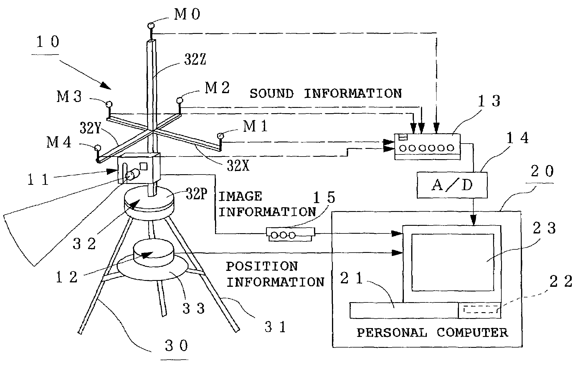
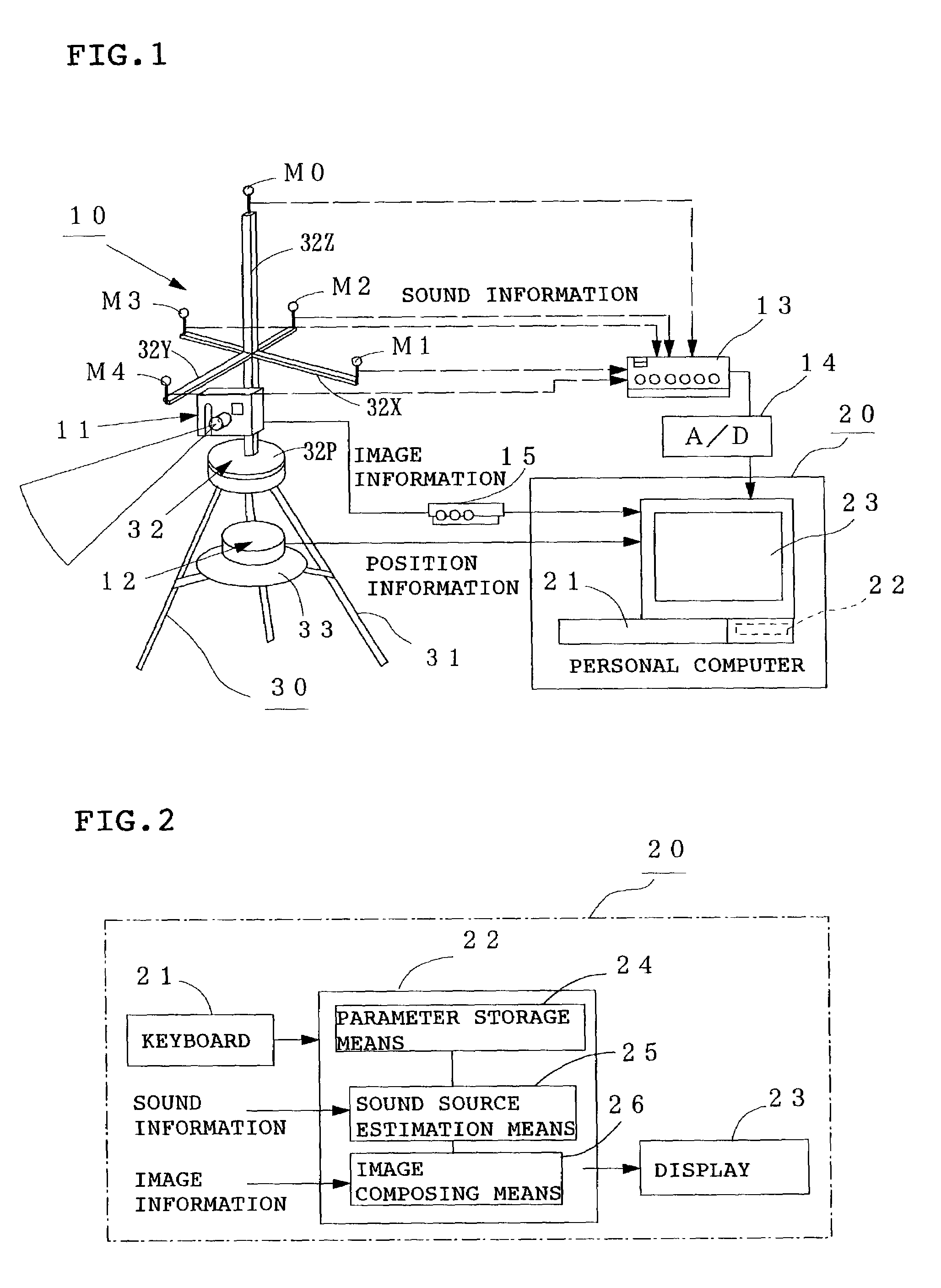
[0033]FIG. 1 is a schematic diagram of a sound source locating system according to Embodiment 1. M1 to M4 are microphones for measuring the sound pressure level of a noise from an unshown sound source, M0 is an auxiliary measuring microphone, 11a CCD camera for picking up an image around the location of the sound source (to be simply referred to as “camera” hereinafter), 12 GPS for specifying the ground positions of the above microphones M0 to M4, 13 amplifier for amplifying sound pressure signals collected by the above microphones M0 to M4, 14 A / D converter for converting the amplified sound pressure signals (analog signals) into digital signals, and 15a video input / output unit for converting the image signal (analog signal) of the camera 11 into a digital signal.
[0034]As shown in FIG. 2, denoted by 20 is a personal computer which comprises a keyboard 21 as input means, a storing / computing unit 22 for computing the estimation of the location of the sound source and a display 23 as ...
embodiment 2
[0063]FIG. 7 is a schematic diagram of a sound source locating system according to Embodiment 2. In this Embodiment, five microphones M1 to M5 arranged in a square columnar form are used to estimate the horizontal angle θ and elevation angle φ of the sound source. Although other elements are the same as in the above Embodiment 1, in this Embodiment 2, sound information from the above microphones M1 to M5 is used to estimate the location of the sound source by means of the personal computer 20.
[0064]A description is subsequently given of an example of the arrangement of the microphones M1 to M5.
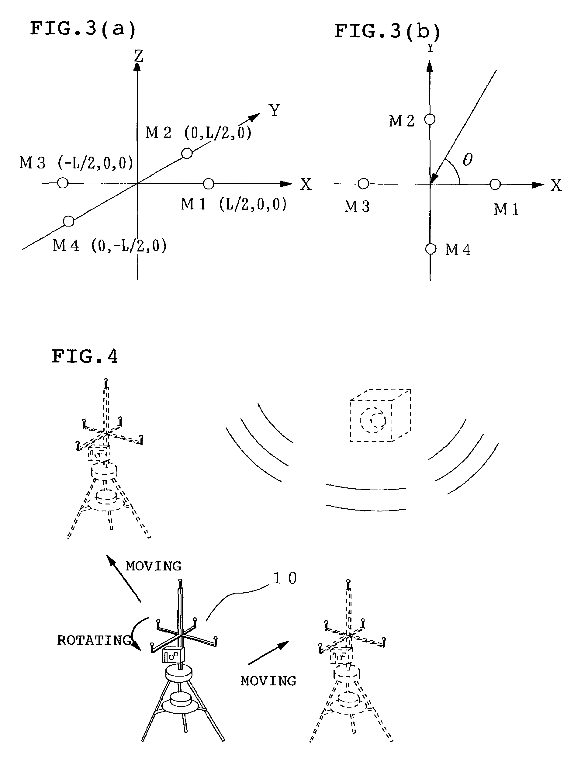
[0065]As shown in FIG. 7 and FIG. 8, the microphones M1 to M4 are disposed above the above rotary frame 32 (in the Z-axis direction) so that their detection portions form a regular square with the origin O on the X-Y plane as the center thereof. Specifically, the detection portions of the microphones M1 and M3 are placed at points (L / 2, 0, 0) and (−L / 2, 0, 0) on the X axis and the detection po...
PUM
 Abstract
Description
Claims
Application Information
 - R&D
- Intellectual Property
- Life Sciences
- Materials
- Tech Scout
- Unparalleled Data Quality
- Higher Quality Content
- 60% Fewer Hallucinations
Browse by: Latest US Patents, China's latest patents, Technical Efficacy Thesaurus, Application Domain, Technology Topic, Popular Technical Reports.
© 2025 PatSnap. All rights reserved.Legal|Privacy policy|Modern Slavery Act Transparency Statement|Sitemap|About US| Contact US: help@patsnap.com


