Eureka AIR delivers breakthrough ideas for toughest innovation challenges, trusted by R&D personnel around the world.

Vehicle frame structure for motorcycles

a vehicle frame and motorcycle technology, applied in the field of motorcycle vehicle frame structure, can solve the problems of reducing productivity, reducing the maneuverability of racing or off-road vehicles, and increasing the size of vehicles, so as to simplify the structure of the vehicle frame, increase the maneuverability of vehicles, and improve productivity

Inactive Publication Date: 2007-01-09
HONDA MOTOR CO LTD
View PDF27 Cites 10 Cited by
  • Summary
  • Abstract
  • Description
  • Claims
  • Application Information

AI Technical Summary

Benefits of technology

[0015]It is therefore an object of the present invention to provide a vehicle frame structure for motorcycles which allows parts to be clustered at the center of the vehicle body, for thereby increasing the maneuvering capability of the vehicle, simplifying the structure of the vehicle frame, improving the productivity at the time the vehicle body is assembled, and reducing the size of the vehicle.
[0017]Since the left and right brackets are independent of each other and are not coupled to each other, a fuel tank, electric parts, or other parts, for example, can be clustered between the left and right brackets. Accordingly, the parts can be disposed near the center of gravity of the vehicle body. Therefore, the maneuvering capability of racing and off-road vehicles incorporating such an arrangement can be increased.
[0018]As compared with a conventional arrangement in which a cross pipe is mounted on a vehicle frame, the vehicle frame constructed of the main frames and the brackets according to the present invention is simple in structure, resulting in a reduction in the cost to manufacture the vehicle frame.
[0019]When the vehicle is assembled, the distance that the worker needs to move can be reduced. Accordingly, the productivity of the vehicle is increased. Furthermore, the size of the vehicle is reduced because of the clustered arrangement of the parts.
[0021]Because the lower ends of the left and right brackets are coupled to each other by the cross beam, a fuel tank, electric parts, or other parts, for example, can be clustered between the upper portions of the left and right brackets. Accordingly, the parts can be disposed near the center of gravity of the vehicle body. Therefore, the maneuvering capability of racing and off-road vehicles incorporating such an arrangement can be increased.

Problems solved by technology

Inasmuch as parts to be disposed in the space between the rear upper portions of the main frames 13 need to be disposed separately in other locations, their weights are distributed, posing disadvantages on racing or off-road vehicles which require high maneuvering capabilities.
This results in a reduction in productivity and an increase in the size of the vehicle.
Accordingly, the manpower required to manufacture the motor vehicle is increased and the cost to manufacture the motor vehicle is also increased.

Method used


Image

  • Vehicle frame structure for motorcycles
  • Vehicle frame structure for motorcycles
  • Vehicle frame structure for motorcycles

Examples


Embodiment Construction

[0032]Embodiments of the present invention will be described below with reference to the accompanying drawings. The figures should be viewed in the direction in which the reference characters are oriented.

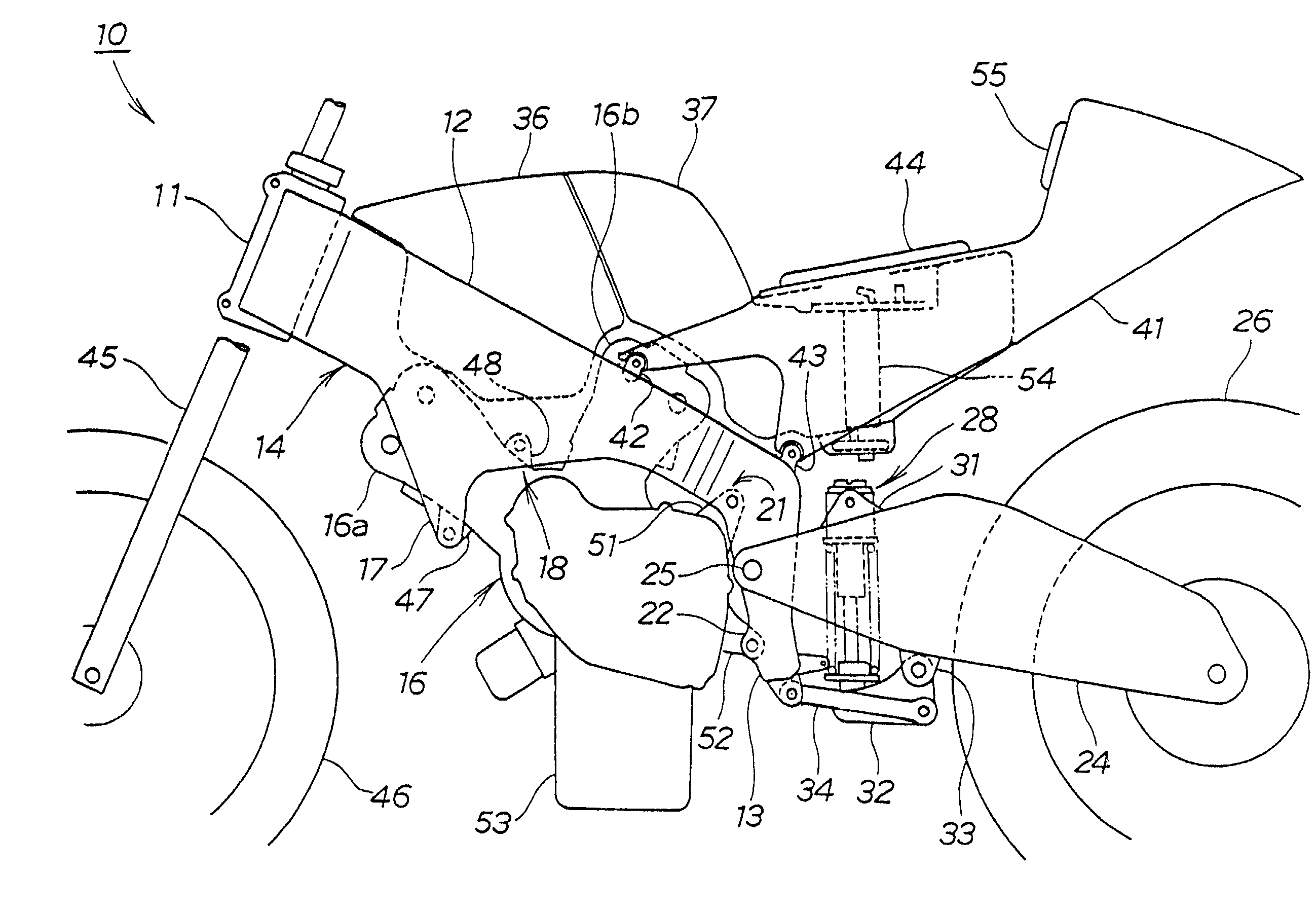
[0033]FIG. 1 is a fragmentary side elevational view of a motorcycle incorporating a vehicle frame structure according to the present invention. The motorcycle 10 includes a vehicle frame 14 having a pair of left and right main frames 12 (the main frame 12 remote from the viewer is not shown) extending rearwardly (specifically, rearwardly and obliquely downwardly) from a head pipe 11. Pivot brackets 13 (the pivot bracket 13 remote from the viewer is not shown) are mounted as brackets on rear portions of the respective main frames 12.

[0034]A V-shaped engine 16 has a front cylinder 16a and a rear cylinder 16b and is mounted on respective engine attachments 17, 18 of the main frames 12 and respective engine attachments 21, 22 of the pivot brackets 13.

[0035]A swing arm24 is swingably mo...


PUM


Abstract

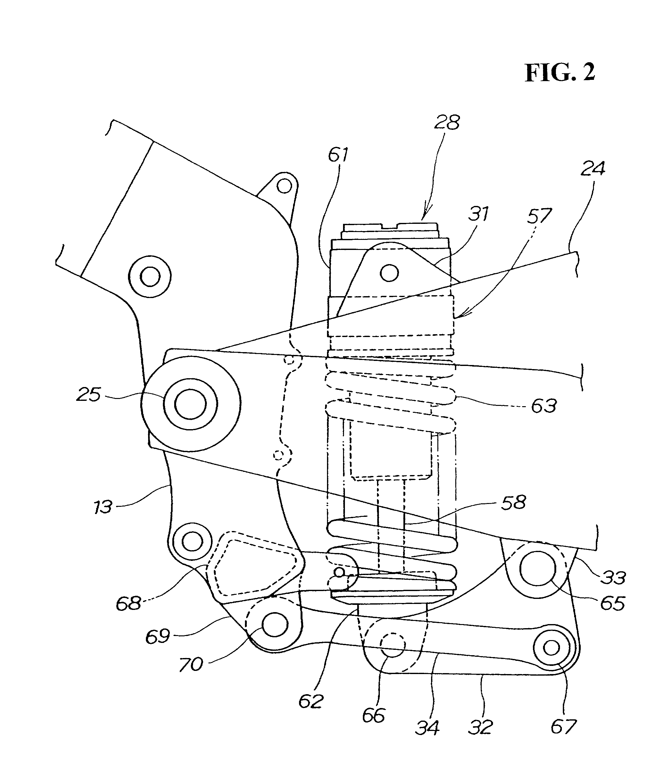
A rear cushion unit has an upper end mounted on a swing arm and a lower end coupled to pivot brackets in a position below a pivot shaft. The pivot brackets are independent of each other and are not coupled to each other. With the above construction, a fuel tank, electric parts, or other parts, for example, can be clustered between the left and right brackets. Accordingly, the parts can be disposed near the center of gravity of the vehicle body. Therefore, the maneuvering capability of racing and off-road vehicles incorporating such an arrangement can be increased. The vehicle frame can be simplified in structure and can be manufactured at a reduced cost. When the vehicle is assembled, the distance that the worker needs to move can be reduced, and hence the productivity of the vehicle is increased. The size of the vehicle is reduced because of the clustered arrangement of the parts.

Description

CROSS-REFERENCES TO RELATED APPLICATIONS[0001]This nonprovisional application claims priority under 35 U.S.C. §119(a) on Patent Application No. 2001-003114 filed in Japan on Jan. 10, 2001.BACKGROUND OF THE INVENTION[0002]1. Field of the Invention[0003]The present invention relates to a vehicle frame structure for motorcycles which is suitable for increasing the maneuvering capability of the vehicle, improving the productivity at the time the vehicle body is assembled, reducing the size of the vehicle, and simplifying the vehicle frame structure.[0004]2. Description of Background Art[0005]Known vehicle frame structures for motorcycles are disclosed in, for example, ① Japanese patent No. 2945094 entitled “Electric two-wheeled vehicle” and ② Japanese patent No. 2963337 entitled “Motorcycle”.[0006]FIG. 5 of the above publication ① shows a motorcycle having left and right main frames 13 extending rearwardly from a head tube 12. A swing arm 24 is swingably mounted on rear portions of the ...

Claims


Application Information

Patent Timeline
Patent Type & Authority Patents(United States)
IPC IPC(8): B62K25/04B62K19/30B62K11/02B62K11/04B62K25/20B62K25/28
CPCB62K11/04B62K25/286B62K25/283B62K11/02
Inventor TOYODA, HIDETOSHIKANAUMI, SHOGOISHIKAWA, YUZURU
Owner HONDA MOTOR CO LTD
Why Eureka
Eureka Blog
Learn More